Nissan Maxima Service and Repair Manual: ECU diagnosis information
TCM
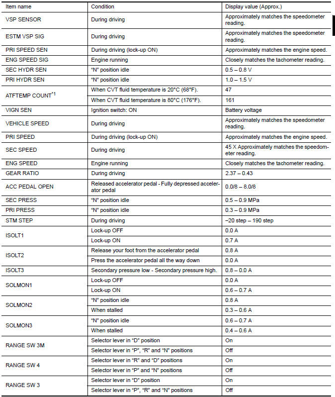
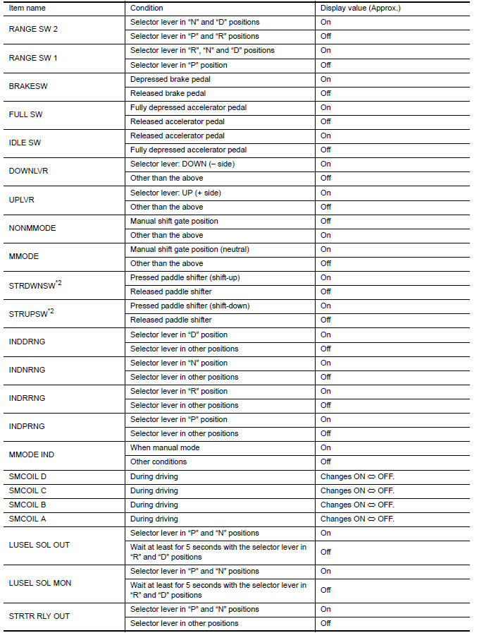
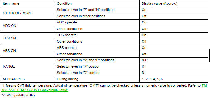
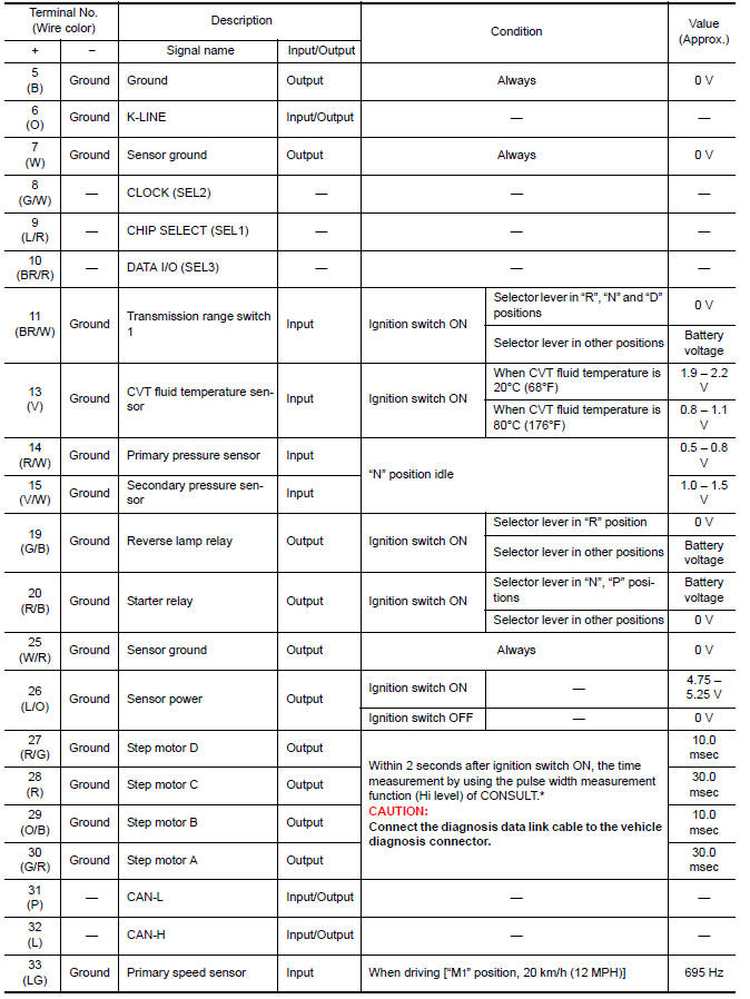
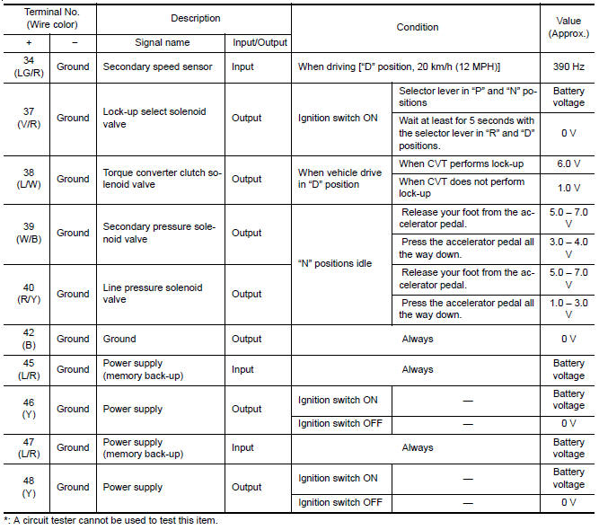
Reference Value
VALUES ON THE DIAGNOSIS TOOL
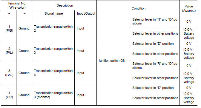
TERMINAL LAYOUT

PHYSICAL VALUES
Fail-safe
The TCM has an electrical fail-safe mode. In this mode TCM operates even if there is an error in a main electronic control input/output signal circuit.
FAIL-SAFE FUNCTION If any malfunction occurs in a sensor or solenoid valve, this function controls the CVT to make driving possible.
Secondary Speed Sensor The shift pattern is changed in accordance with the throttle position when an unexpected signal is sent from the secondary speed sensor to the TCM. The manual mode and "DS" mode are inhibited, and the transaxle is put in "D".
Primary Speed Sensor The shift pattern is changed in accordance with the throttle position and secondary speed (vehicle speed) when an unexpected signal is sent from the primary speed sensor to the TCM. The manual mode and "DS" mode are inhibited, and the transaxle is put in "D".
Transmission Range Switch If an unexpected signal is sent from the transmission range switch to the TCM, the transaxle is put in "D".
CVT Fluid Temperature Sensor
If an unexpected signal is sent from the CVT fluid temperature sensor to the TCM, the gear ratio in use before receiving the unexpected signal is maintained or the gear ratio is controlled to keep engine speed under 5,000 rpm.
Secondary Pressure Sensor
-
If an unexpected signal is sent from the secondary pressure sensor to the TCM, the secondary pressure feedback control is stopped and the offset value obtained before the non-standard condition occurs is used to control line pressure.
-
If secondary pressure sensor error signal is inputted to the TCM, secondary pressure feedback control stops, but line pressure is controlled normally.
Line Pressure Solenoid Valve
If an unexpected signal is sent from the solenoid valve to the TCM, the line pressure solenoid valve is turned OFF to achieve the maximum fluid pressure.
Secondary Pressure Solenoid Valve
If an unexpected signal is sent from the solenoid valve to the TCM, the secondary pressure solenoid valve is turned OFF to achieve the maximum fluid pressure.
Torque Converter Clutch Solenoid Valve
If an unexpected signal is sent from the solenoid valve to the TCM, the torque converter clutch solenoid valve is turned OFF to cancel the lock-up.
Step Motor
If an unexpected signal is sent from the step motor to the TCM, the step motor coil phases "A" through "D" are all turned OFF to hold the gear ratio used just before the non-standard condition occurred.
Lock-up Select Solenoid Valve
If an unexpected signal is sent from the solenoid valve to the TCM, the lock-up select solenoid valve is turned OFF to cancel the lock-up.
TCM Power Supply (Memory Back-up)
Transaxle assembly is protected by limiting the engine torque when the memory back-up power supply (for controlling) from the battery is not supplied to the TCM. Normal status is restored when turning the ignition switch OFF to ON after the normal power supply.
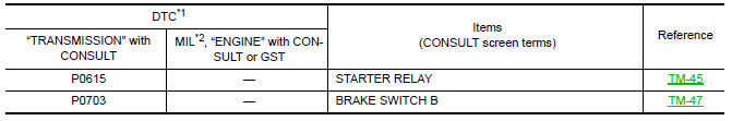
DTC Inspection Priority Chart
If some DTCs are displayed at the same time, perform inspections one by one based on the following priority chart.
NOTE: If DTC "U0100/U1000/U1010/P1709" is indicated with other DTCs, start from a diagnosis for DTC "U0100/U1000/U1010/P1709". Refer to TM-42 (U0100), TM-43 (U1000), TM-44 (U1010), TM-99 (P1709).

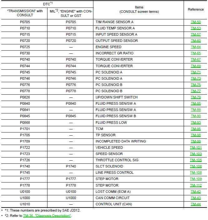
DTC Index
NOTE: If DTC "U0100/U1000/U1010/P1709" is indicated with other DTCs, start from a diagnosis for DTC "U0100/U1000/U1010/P1709". Refer to TM-42 (U0100), TM-43 (U1000), TM-44 (U1010), TM-99 (P1709).
 Shift lock system
Description
The selector lever cannot be shifted from "P" position to
any other position unless the ignition switch is in the
ON position and the brake pedal is depressed.
Component Function Che ...
 Wiring diagram
CVT CONTROL SYSTEM
Wiring Diagram
...
Other materials:
B2604 transmission range switch
Description
BCM confirms the shift position with the following 4
signals.
CVT selector lever
Transmission range switch
P position signal from IPDM E/R (CAN)
P position signal from TCM (CAN)
DTC Logic
DTC DETECTION LOGIC
NOTE:
I ...
Basic inspection
DIAGNOSIS AND REPAIR WORKFLOW
Work Flow
OVERALL SEQUENCE
DETAILED FLOW
1.OBTAIN INFORMATION ABOUT SYMPTOM
Interview the customer to obtain as much information as possible about the
conditions and environment under
which the malfunction occurred.
>> GO TO 2
2.CHECK SYMPTOM
Chec ...
Subwoofer
Removal and Installation
Subwoofer (LH)
Subwoofer (RH)
Subwoofer screws
Subwoofer connectors
REMOVAL
Remove the rear parcel shelf finisher. Refer to INT-28, "Removal
and Installation".
Remove the subwoofer screws.
Pull out the subwoofer, disconnect the harne ...
Nissan Maxima Owners Manual
- Illustrated table of contents
- Safety-Seats, seat belts and supplemental restraint system
- Instruments and controls
- Pre-driving checks and adjustments
- Monitor, climate, audio, phone and voice recognition systems
- Starting and driving
- In case of emergency
- Appearance and care
- Do-it-yourself
- Maintenance and schedules
- Technical and consumer information
Nissan Maxima Service and Repair Manual

0.0058