Nissan Maxima Service and Repair Manual: Shift lock system
Description
The selector lever cannot be shifted from "P" position to any other position unless the ignition switch is in the ON position and the brake pedal is depressed.
Component Function Check
1. CHECK CVT SHIFT LOCK OPERATION
-
Turn ignition switch ON.
-
Move selector lever to "P" position.
-
Attempt to shift selector lever to any other position with brake pedal released.
2. CHECK CVT SHIFT LOCK OPERATION
Attempt to shift selector lever to any other position with brake pedal depressed.
Diagnosis Procedure
Regarding Wiring Diagram information, refer to TM-134, "Wiring Diagram".
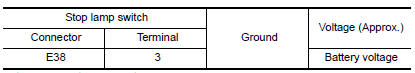
1. CHECK POWER SOURCE (STOP LAMP SWITCH)
-
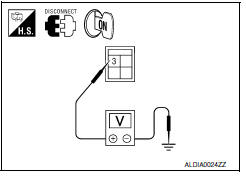
Turn ignition switch OFF.
-
Disconnect stop lamp switch connector.
-
Check voltage between stop lamp switch connector E38 terminal 3 and ground.
2.CHECK STOP LAMP SWITCH
Check stop lamp switch. Refer to TM-118, "Component Inspection (Stop Lamp Switch)".
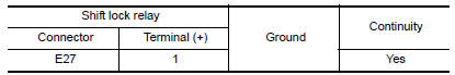
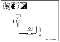
3.CHECK GROUND CIRCUIT (SHIFT LOCK RELAY)
-
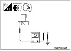
Remove shift lock relay.
-
Check continuity between shift lock relay connector E27 terminal 1 and ground.
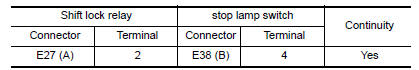
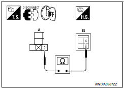
4.CHECK HARNESS BETWEEN SHIFT LOCK RELAY AND STOP LAMP SWITCH FOR OPEN
Check continuity between shift lock relay connector E27 (A) terminal 2 and stop lamp switch connector E38 (B) terminal 4.
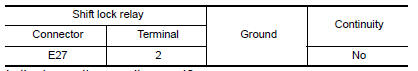
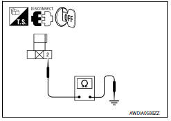
5.CHECK HARNESS BETWEEN SHIFT LOCK RELAY AND STOP LAMP SWITCH FOR SHORT CIRCUIT
Check continuity between shift lock relay connector E27 terminal 2 and ground.
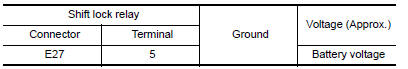
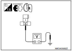
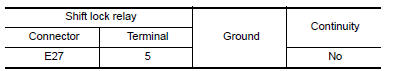
6.CHECK POWER SOURCE (SHIFT LOCK RELAY)
-
Turn ignition switch ON.
-
Check voltage between shift lock relay connector E27 terminal 5 and ground.
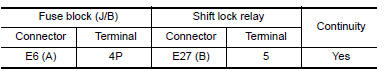
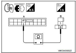
7.CHECK HARNESS BETWEEN FUSE BLOCK (J/B) AND SHIFT LOCK RELAY FOR OPEN
-
Turn ignition switch OFF.
-
Disconnect fuse block (J/B).
-
Check continuity between fuse block (J/B) connector E6 (A) terminal 4P and shift lock relay connector E27 (B) terminal 5.
8.CHECK HARNESS BETWEEN FUSE BLOCK (J/B) AND SHIFT LOCK RELAY FOR SHORT CIRCUIT
Check continuity between shift lock relay connector E27 terminal 5 and ground.
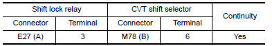
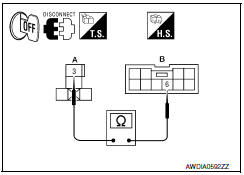
9.CHECK HARNESS BETWEEN SHIFT LOCK RELAY AND CVT SHIFT SELECTOR FOR OPEN
-
Disconnect CVT shift selector connector.
-
Check continuity between shift lock relay connector E27 (A) terminal
-
and CVT shift selector connector M78 (B) terminal 6.
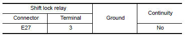
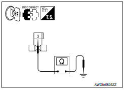
10.CHECK HARNESS BETWEEN SHIFT LOCK RELAY AND CVT SHIFT SELECTOR FOR SHORT CIRCUIT
Check continuity between shift lock relay connector E27 terminal 3 and ground.
11.CHECK SHIFT LOCK RELAY
Check shift lock relay. Refer to TM-118, "Component Inspection (Shift Lock Relay)".
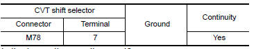
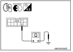
12.CHECK GROUND CIRCUIT (CVT SHIFT SELECTOR)
Check continuity between CVT shift selector connector M78 terminal 7 and ground.
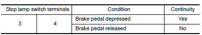
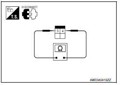
1.CHECK STOP LAMP SWITCH
Check continuity between stop lamp switch terminals.
Component Inspection (Shift Lock Relay)
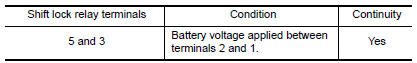
1.CHECK SHIFT LOCK RELAY
-
Apply battery voltage between terminals 2 and 1 of the shift lock relay.
CAUTION: Connect a fuse between the terminals when applying battery voltage.
-
Check continuity between shift lock relay terminals 5 and 3.
 Shift position indicator circuit
Description
TCM sends position indicator signals to
combination meter via CAN communication line.
The selector lever position is indicated on the
shift position indica ...
 ECU diagnosis information
TCM
Reference Value
VALUES ON THE DIAGNOSIS TOOL
TERMINAL LAYOUT
PHYSICAL VALUES
Fail-safe
The TCM has an electrical fail-safe mode. In this mode
TCM operates even if there is an ...
Other materials:
Turning the FEB system on/off
Perform the following steps to turn the FEB systems
ON or OFF.
1. Press the button until
"Settings" displays
in the vehicle information display and
then press OK button. Use the
button
to select "Driver Assistance". Then press the
OK button.
2. Select "Emergency Brake" ...
Jump starting
To start your engine with a booster battery, the
instructions and precautions below must be followed.
WARNING
If done incorrectly, jump starting can
lead to a battery explosion, resulting in
severe injury or death. It could also
damage your vehicle.
Explosive hydrogen gas is always pre ...
Ground
Ground Distribution
MAIN HARNESS
ENGINE ROOM HARNESS
FRONT END MODULE HARNESS
ENGINE CONTROL HARNESS
BODY HARNESS
BODY NO. 2 HARNESS
...
Nissan Maxima Owners Manual
- Illustrated table of contents
- Safety-Seats, seat belts and supplemental restraint system
- Instruments and controls
- Pre-driving checks and adjustments
- Monitor, climate, audio, phone and voice recognition systems
- Starting and driving
- In case of emergency
- Appearance and care
- Do-it-yourself
- Maintenance and schedules
- Technical and consumer information
Nissan Maxima Service and Repair Manual

0.0055