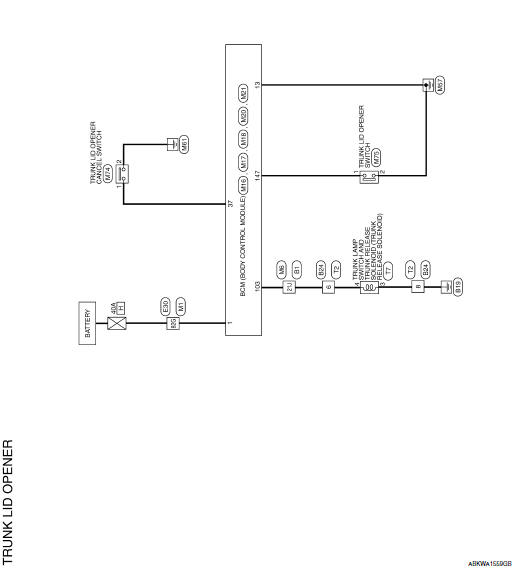
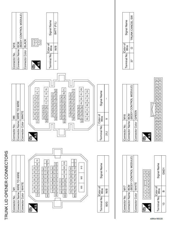
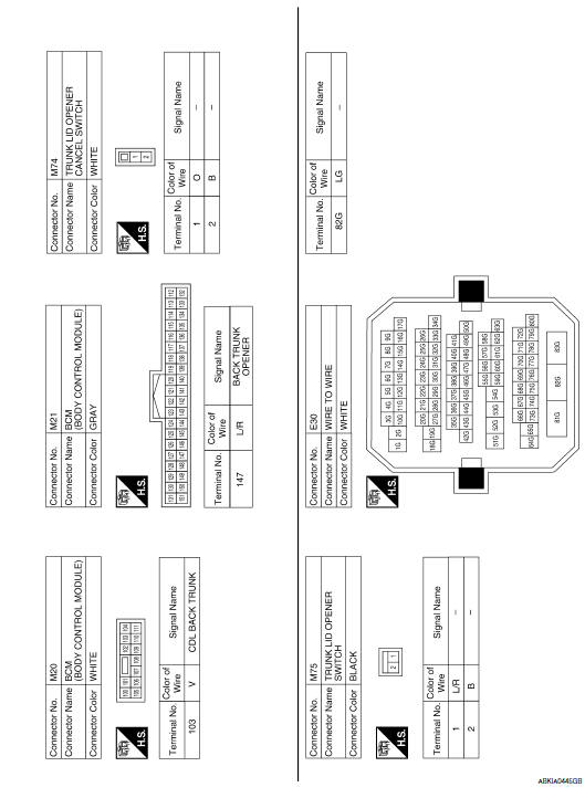
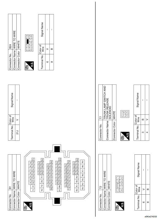
Nissan Maxima Service and Repair Manual: Trunk lid opener
Wiring Diagram
 Intelligent key system
Wiring Diagram
...
 Homelink universal transceiver
Wiring Diagram
...
Other materials:
Rear lower link & coil spring
Removal and Installation
Removal
Remove the rear wheel and tire using power tool. Refer to WT-60,
"Adjustment".
Loosen the rear lower link adjusting bolt and nut at the rear
suspension member.
Support the rear lower link with a suitable jack.
Support the rear axle housing with a ...
Checking lights
Anti-lock Braking System (ABS)
warning light
Brake warning light (parking brake)
Brake warning light
Charge warning light
Engine oil pressure warning light
Forward Emergency Braking (FEB) system warning
light (if so eq ...
Id registration cannot be completed
ID Registration Cannot Be Completed
NOTE: The Signal Tech II Tool (J-50190) can be used
to perform the following functions. Refer to the Signal Tech II User Guide
for additional information.
Activate and display TPMS transmitter IDs
Display tire pressure reported by the TPMS t ...
Nissan Maxima Owners Manual
- Illustrated table of contents
- Safety-Seats, seat belts and supplemental restraint system
- Instruments and controls
- Pre-driving checks and adjustments
- Monitor, climate, audio, phone and voice recognition systems
- Starting and driving
- In case of emergency
- Appearance and care
- Do-it-yourself
- Maintenance and schedules
- Technical and consumer information
Nissan Maxima Service and Repair Manual

0.0058