Nissan Maxima Service and Repair Manual: Homelink universal transceiver
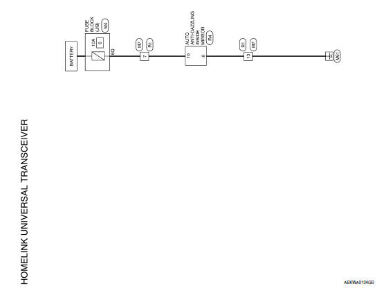
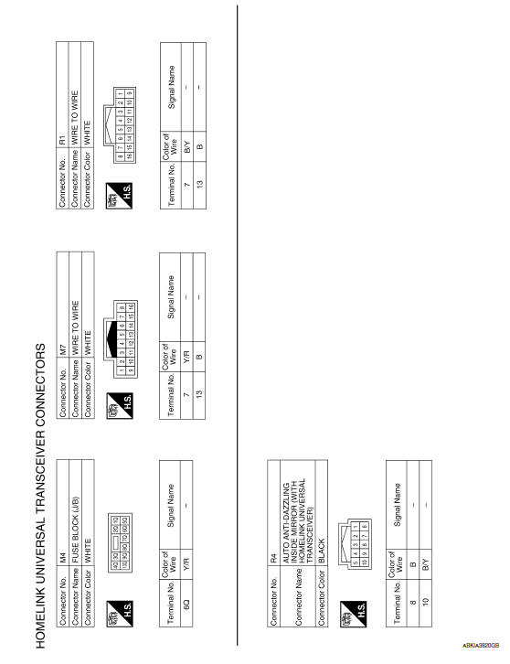
Wiring Diagram
 Trunk lid opener
Wiring Diagram
...

Other materials:
Inspection and adjustment
ADDITIONAL SERVICE WHEN REPLACING CONTROL UNIT
ADDITIONAL SERVICE WHEN REPLACING CONTROL UNIT : Description
MEMORY RESET PROCEDURE
Please observe the following instructions at confirming the sunroof
operation. NOTE: Do not
disconnect the electronic power while the sunroof is operating or ...
ABS branch line circuit
Diagnosis Procedure
1.CHECK CONNECTOR
Turn the ignition switch OFF.
Disconnect the battery cable from the negative terminal.
Check the terminals and connectors of the ABS actuator and
electric unit (control unit) for damage, bend
and loose connection (unit side and connector side).
...
Handling precautions for plastics
Precautions For Plastics
When repairing and painting a portion of the body adjacent to plastic
parts, consider their characteristics
(influence of heat and solvent) and remove them if necessary or take
suitable measures to protect them.
Plastic parts should be repaired and painted ...
Nissan Maxima Owners Manual
- Illustrated table of contents
- Safety-Seats, seat belts and supplemental restraint system
- Instruments and controls
- Pre-driving checks and adjustments
- Monitor, climate, audio, phone and voice recognition systems
- Starting and driving
- In case of emergency
- Appearance and care
- Do-it-yourself
- Maintenance and schedules
- Technical and consumer information
Nissan Maxima Service and Repair Manual

0.007