
Nissan Maxima Service and Repair Manual: Microphone signal circuit
Description
Voice signals are transmitted from the microphone to the Bluetooth control unit using the microphone signal circuits.
Diagnosis Procedure
1.CHECK HARNESS BETWEEN BLUETOOTH CONTROL UNIT AND MICROPHONE
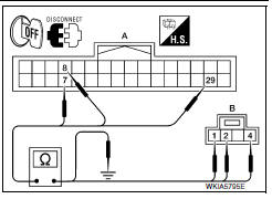
- Turn ignition switch OFF.
- Disconnect Bluetooth control unit connector and microphone connector.
- Check continuity between Bluetooth control unit harness connector B126 (A) and microphone harness connector R7 (B)
- Check continuity between Bluetooth control unit harness connector B126 (A) and ground.
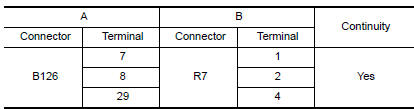

2.CHECK MICROPHONE POWER SUPPLY
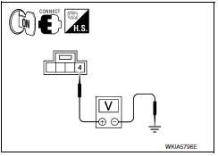
- Connect Bluetooth control unit connector and microphone connector.
- Turn ignition switch ON.
- Check voltage between microphone harness connector R7 terminal 4 and ground.

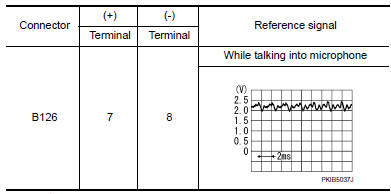
3.CHECK MICROPHONE SIGNAL
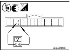
Check signal between Bluetooth control unit harness connector B126 terminals 7 and 8.
 Steering switch
Description
When one of the steering wheel audio control switches is pushed, the
resistance in steering switch circuit changes depending on which button is
pushed.
Diagnosis Procedure
1.CHECK S ...

Other materials:
P1722 vehicle speed
Description
The vehicle speed signal is transmitted from ABS actuator
and electric unit (control unit) to TCM via CAN communication
line.
DTC Logic
DTC DETECTION LOGIC
DTC CONFIRMATION PROCEDURE
CAUTION:
Always drive vehicle at a safe speed.
NOTE:
Immediately after performing any "DT ...
RGB (R: red) signal circuit
Description
Transmit the image displayed with AV control unit with RGB signal to the
display unit.
Diagnosis Procedure
1.CHECK CONTINUITY RGB (R: RED) SIGNAL CIRCUIT
Turn ignition switch OFF.
Disconnect display unit connector M141 and AV control unit
connector M117.
Check continu ...
Horn function
Symptom Table
HAZARD AND HORN REMINDER FUNCTION MALFUNCTION
NOTE:
Before performing the diagnosis in the following table, check
"Work flow". Refer to DLK-9, "Work Flow".
If the following symptoms are detected, check systems shown in
the "Diagnosis/service procedure" column
...
Nissan Maxima Owners Manual
- Illustrated table of contents
- Safety-Seats, seat belts and supplemental restraint system
- Instruments and controls
- Pre-driving checks and adjustments
- Monitor, climate, audio, phone and voice recognition systems
- Starting and driving
- In case of emergency
- Appearance and care
- Do-it-yourself
- Maintenance and schedules
- Technical and consumer information
Nissan Maxima Service and Repair Manual

0.01