Nissan Maxima Service and Repair Manual: Steering switch
Description
When one of the steering wheel audio control switches is pushed, the resistance in steering switch circuit changes depending on which button is pushed.
Diagnosis Procedure
1.CHECK STEERING SWITCH RESISTANCE
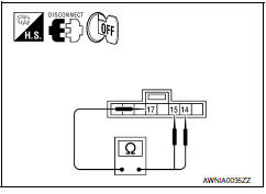
- Disconnect steering switch connector M88.
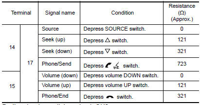
- Check resistance between steering switch connector terminals.
2.CHECK HARNESS BETWEEN COMBINATION SWITCH (SPIRAL CABLE) AND BLUETOOTH CONTROL UNIT
- Turn ignition switch OFF.
- Disconnect Bluetooth control unit connector B126 and combination switch (spiral cable) connector M30
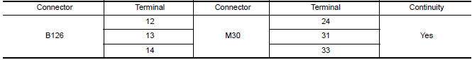
- Check continuity between Bluetooth control unit harness connector B126 and combination switch (spiral cable) harness connector M30.
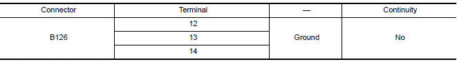
- Check continuity between Bluetooth control unit connector B126 and ground.
3.CHECK HARNESS BETWEEN COMBINATION SWITCH (SPIRAL CABLE) AND AUDIO UNIT
- Disconnect audio unit connector M147.
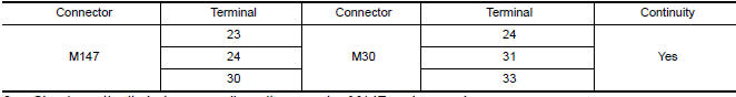
- Check continuity between audio unit harness connector M147 and combination switch (spiral cable) harness connector M30.
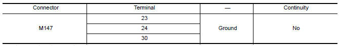
- Check continuity between audio unit connector M147 and ground.
4.COMBINATION SWITCH (SPIRAL CABLE) CHECK
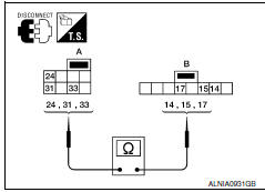
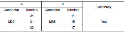
- Check continuity between combination switch (spiral cable) harness connector M30 (A) and M88 (B).
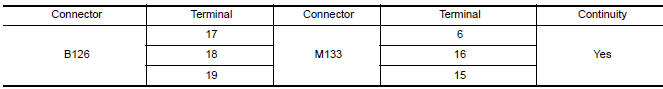
5.CHECK HARNESS BETWEEN BLUETOOTH CONTROL UNIT AND AUDIO UNIT
- Disconnect audio unit connector M133.
- Check continuity between Bluetooth control unit harness connector B126 and audio unit harness connector M133.
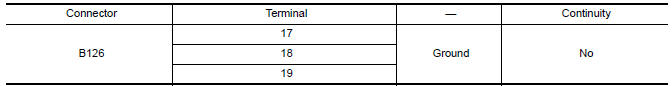
- Check continuity between Bluetooth control unit connector B126 and ground.
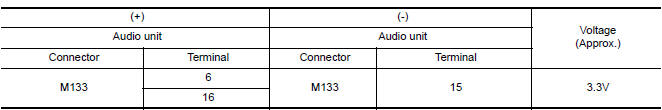
6.CHECK AUDIO UNIT VOLTAGE
- Connect audio unit harness connector M133 and Bluetooth control unit harness connector B126.
- Turn ignition switch ON.
- Check voltage between audio unit harness connector M133 terminals.
 Subwoofer
Description
The audio unit sends audio signals to the subwoofer amp. The subwoofer amp.
amplifies the audio signals before sending them to the subwoofers using the
audio signal circuits.
Diagnos ...
 Microphone signal circuit
Description
Voice signals are transmitted from the microphone to the Bluetooth control
unit using the microphone signal circuits.
Diagnosis Procedure
1.CHECK HARNESS BETWEEN BLUETOOTH CONTROL UNI ...
Other materials:
Daytime running light system
Wiring Diagram
...
Daytime running light system
Wiring Diagram
...
Transverse link
Removal and Installation
REMOVAL
Remove front wheel and tire using power tool. Refer to WT-60,
"Adjustment".
Remove the knuckle spindle bolt and nut at the transverse link.
Remove the steering knuckle from the transverse link using Tool.
Refer to FSU-13, "Exploded View".
Tool numbe ...
Nissan Maxima Owners Manual
- Illustrated table of contents
- Safety-Seats, seat belts and supplemental restraint system
- Instruments and controls
- Pre-driving checks and adjustments
- Monitor, climate, audio, phone and voice recognition systems
- Starting and driving
- In case of emergency
- Appearance and care
- Do-it-yourself
- Maintenance and schedules
- Technical and consumer information
Nissan Maxima Service and Repair Manual

0.0085