Nissan Maxima Service and Repair Manual: Transverse link
Removal and Installation
REMOVAL
- Remove front wheel and tire using power tool. Refer to WT-60, "Adjustment".
- Remove the knuckle spindle bolt and nut at the transverse link.
- Remove the steering knuckle from the transverse link using Tool. Refer to FSU-13, "Exploded View".
Tool number : HT7252000 (J-25730-B)
- Remove the stabilizer connecting rod nut at the front stabilizer.
- Slightly loosen the transverse link bolts.
- Remove the transverse link bolts and nuts. Remove the transverse link from the front suspension member.
INSPECTION AFTER REMOVAL
Visual Inspection
Check transverse link and bushing for deformation, cracks, and other damage. Replace the entire transverse link assembly if cracks, deformation or any other damage is found.
Ball Joint Inspection
CAUTION: Before measurement, move the ball joint at least ten times by hand to check for smooth movement.
Swing Torque Inspection
- Hook Tool at cutout on ball stud. Confirm Tool measurement value is within specifications when ball stud begins moving.
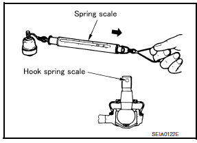
Tool number : - (J-44372)
Swing torque : Refer to FSU-18, "Ball
Joint".
Measurement on spring balance : Refer to FSU-18, "Ball
Joint"
- If the value is outside the standard, replace transverse link.
Axial End Play Inspection
- Move tip of ball joint in axial direction to check for looseness.
Axial end play : Refer to FSU-18, "Ball Joint".
- If any looseness is noted, replace transverse link.
INSTALLATION
Installation is in the reverse order of removal.
CAUTION: Do not reuse the transverse link nuts at the front suspension member.
- Tighten transverse link bolts with vehicle unladen and all four tires on flat, level ground. Refer to FSU-13, "Exploded View".
- After installation, check wheel alignment. Refer to FSU-6, "Inspection and Adjustment".
 Front coil spring and strut
Removal and Insallation
REMOVAL
Remove front wheel and tire using power tool. Refer to WT-60,
"Adjustment".
Remove the wheel sensor harness from the front coil spring and
strut. Refer to ...
 Front stabilizer
Removal and Installation
REMOVAL
Remove the steering gear and linkage. Refer to ST-26, "Removal and
Installation".
Remove the nuts on the upper portion of stabilizer connecting
rod
Re ...
Other materials:
Unit disassembly and assembly
COMBINATION METER
Disassembly and Assembly
DISASSEMBLY
Remove the combination meter. Refer to MWI-122,
"Removal and Installation".
Remove the combination meter lens (1) from the
combination
meter (2).
ASSEMBLY
Assembly is in the reverse order of disasse ...
C1143, C1144 steering angle sensor
Description
The steering angle sensor detects the rotation amount, angular velocity and
direction of the steering wheel,
and transmits the data to the ABS actuator and electric unit (control unit) via
CAN communication.
DTC Logic
DTC DETECTION LOGIC
DTC CONFIRMATION PROCEDURE
1.CHECK ...
Headlamp
Wiring Diagram
...
Nissan Maxima Owners Manual
- Illustrated table of contents
- Safety-Seats, seat belts and supplemental restraint system
- Instruments and controls
- Pre-driving checks and adjustments
- Monitor, climate, audio, phone and voice recognition systems
- Starting and driving
- In case of emergency
- Appearance and care
- Do-it-yourself
- Maintenance and schedules
- Technical and consumer information
Nissan Maxima Service and Repair Manual

0.0063