Nissan Maxima Service and Repair Manual: Road wheel tire assembly
Adjustment
BALANCING WHEELS (ADHESIVE WEIGHT TYPE)
Preparation Before Adjustment Remove inner and outer balance weights from the road wheel. Using releasing agent, remove double-faced adhesive tape from the road wheel.
CAUTION:
- Be careful not to scratch the road wheel during removal.
- After removing double-faced adhesive tape, wipe clean all traces of releasing agent from the road wheel.
Wheel Balance Adjustment
- If a balancer machine has an adhesive weight mode setting, select the adhesive weight mode setting and skip Step 2. below. If a balancer machine only has the clip-on (rim flange) weight mode setting, follow Step 2. to calculate the correct size adhesive weight.
- Set road wheel on balancer machine using the center hole as a guide. Start the balancer machine.
- For balancer machines that only have a clip-on (rim flange) weight mode setting, follow this step to calculate the correct size adhesive weight to use. When inner and outer imbalance values are shown on the balancer machine indicator, multiply outer imbalance value by 5/3 (1.67) to determine balance weight that should be used. Select the outer balance weight with a value closest to the calculated value above and install in to the designated outer position of, or at the designated angle in relation to the road wheel.
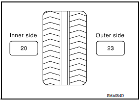
- Indicated imbalance value × 5/3 = balance weight to be installed Calculation example: 23 g (0.81 oz) × 5/3 (1.67) = 38.33 g (1.35 oz) ⇒ 40 g (1.41 oz) balance weight (closer to calculated balance weight value)
NOTE: Note that balance weight value must be closer to the calculated balance weight value.
Example:
37.4 ⇒ 35 g (1.23 oz)
37.5 ⇒ 40 g (1.41 oz)
- Install balance weight in the position shown.
CAUTION:
- Do not install the inner balance weight before installing the outer balance weight.
- Before installing the balance weight, be sure to clean the mating surface of the road wheel.
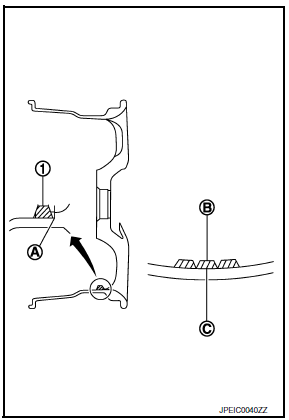
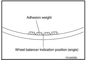
- When installing balance weight (1) to road wheel, set it into the grooved area (A) on the inner wall of the road wheel as shown so that the balance weight center (B) is aligned with the balancer machine indication position (angle) (C).
CAUTION:
- Always use Genuine NISSAN adhesive balance weights.
- Balance weights are non-reusable; always replace with new ones.
- Do not install more than three sheets of balance weight.
- If calculated balance weight value exceeds 50 g (1.76 oz), install
two balance weight sheets in line with each other as shown.
CAUTION: Do not install one balance weight sheet on top another. - Start balancer machine again.
- Install balance weight on inner side of road wheel in the balancer machine indication position (angle). CAUTION: Do not install more than two balance weights.
- Start balancer machine. Make sure that inner and outer residual imbalance values are 5 g (0.17 oz) each or below.
- If either residual imbalance value exceeds 5 g (0.17 oz), repeat installation procedures.
TIRE ROTATION
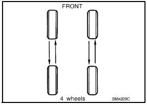
- Use power tool to remove wheel and tire assembly.
- Follow the maintenance schedule for tire rotation service intervals.
Refer to MA-5, "FOR USA AND CANADA : Explanation of General Maintenance" (United States and Canada), MA-7, "FOR MEXICO : Explanation of General Maintenance" (Mexico).
CAUTION:
- Do not include the T-type spare tire when rotating the tires.
- When installing wheels, tighten them diagonally by dividing the work two to three times in order to prevent the wheels from developing any distortion.
- Be careful not to tighten wheel nut at torque exceeding the criteria for preventing strain of disc rotor.
 Tire pressure receiver
Removal and Installation
REMOVAL
Remove instrument lower panel LH. Refer to IP-11, "Removal and
Installation".
Locate tire pressure receiver (1) to the right of the steering column
an ...
 Unit removal and installation
TRANSMITTER
Exploded View
Transmitter (tire pressure sensor)
O-ring
Valve stem nut
Valve core
Valve cap
Valve stem assembly : Parts that are
replaced as a set when the tire is ...
Other materials:
Engine coolant temperature gauge
The gauge indicates the engine coolant temperature.
The engine coolant temperature is within the
normal range 1 when the gauge needle points
within the zone shown in the illustration.
The engine coolant temperature varies with the
outside air temperature and driving conditions.
CAUTION ...
Automatic drive positioner (if so equipped)
The automatic drive positioner system has three
features:
Memory storage function (Key-link)
Memory storage function (Switch)
Entry/exit function
Key-link, when enabled, automatically retains the
driver's last seat, automatic steering wheel, and
outside mirror positions for that specif ...
Rear-facing child restraint installation using LATCH
For additional information, refer to all Warnings
and Cautions in the "Child safety" and "Child
restraints" sections of this manual before installing
a child restraint.
Do not use the lower anchors if the combined
weight of the child and the child restraint exceeds
65 lbs (29.5 kg). If the c ...
Nissan Maxima Owners Manual
- Illustrated table of contents
- Safety-Seats, seat belts and supplemental restraint system
- Instruments and controls
- Pre-driving checks and adjustments
- Monitor, climate, audio, phone and voice recognition systems
- Starting and driving
- In case of emergency
- Appearance and care
- Do-it-yourself
- Maintenance and schedules
- Technical and consumer information
Nissan Maxima Service and Repair Manual

0.0066