
Nissan Maxima Service and Repair Manual: Unit removal and installation
TRANSMITTER
Exploded View
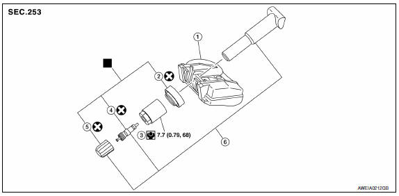
- Transmitter (tire pressure sensor)
- O-ring
- Valve stem nut
- Valve core
- Valve cap
- Valve stem assembly
 : Parts that are
replaced as a set when the tire is replaced.
: Parts that are
replaced as a set when the tire is replaced.
Removal and Installation
REMOVAL
- Remove road wheel and tire assembly using power tool. Refer to WT-60, "Adjustment".
- Remove valve cap and valve core to deflate the tire.
NOTE: If the tire is to be reused, apply a matching mark on the tire in line with the position of the road wheel valve stem assembly for the purpose of road wheel and tire balance adjustment after installation.
- Remove the valve stem nut and allow transmitter to fall into tire.
- Lubricate the tire outside bead well with a suitable non-silicone lubricant, and remove outside of tire from the road wheel. Reach inside the tire and remove the transmitter.
CAUTION:
- Do not use silicone lubricant. Use of silicone lubricant will deteriorate the tire and road wheel.
- Be sure not to damage the road wheel or transmitter.
- Do not allow lubricant to make contact with transmitter.
- Lubricate the tire inside bead well with a suitable non-silicone lubricant, and remove inside of tire from the road wheel.
CAUTION:
- Do not use silicone lubricant. Use of silicone lubricant will deteriorate the tire and road wheel.
- Be sure not to damage the road wheel.
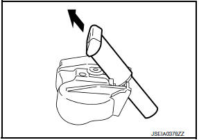
- Remove the valve stem from the transmitter as shown.
INSTALLATION
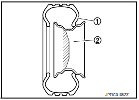
- Apply a suitable non-silicone lubricant to the tire inside bead. CAUTION: Do not use silicone lubricant. Use of silicone lubricant will deteriorate the tire and wheel.
- Install the tire inside bead (1) onto the road wheel (2) in the position shown.
- Install the valve stem to the transmitter.
- Install the O-ring to the transmitter.
CAUTION:
- Do not reuse O-ring
- Insert O-ring to the base of the transmitter.
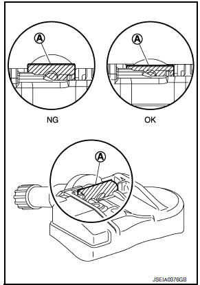
- The base of the valve stem (A) must be positioned in the groove of the metal plate as shown.
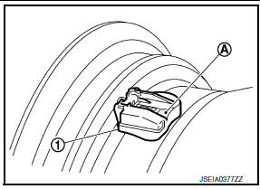
- Install transmitter (1) to road wheel while pressing at position (A).
CAUTION:
- Check that O-ring contacts horizontally with road wheel.
- Check that the base of the valve stem is positioned in the groove of the metal plate.
- Install and tighten the valve stem nut to the specified torque.
Valve stem nut tightening torque : 7.7 N*m (0.79 kg-m, 68 in-lb
CAUTION: Do not use power tool for installation.
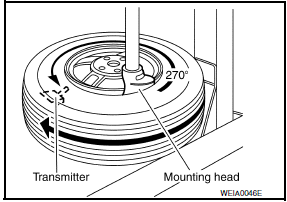
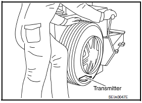
- Place wheel on turntable of tire machine. Ensure that transmitter is
270 degrees from mounting/dismounting head.
NOTE: Do not touch transmitter with mounting head. - Apply a suitable non-silicone lubricant to the tire outside bead.
CAUTION:
- Do not use silicone lubricant. Use of silicone lubricant will deteriorate the tire and wheel.
- Do not allow lubricant to make contact with transmitter.
- Install the tire outside bead onto the road wheel as normal. NOTE: If the tire is being reused, align the matching mark applied on the tire with the position of the road wheel valve stem assembly for the purpose of road wheel and tire balance adjustment after installation. Ensure that the tire does not rotate relative to road wheel.
- Install the valve core and inflate tire.
CAUTION: Do not reuse valve core.
- Install the valve cap.
CAUTION: Do not reuse valve cap. - Balance the road wheel and tire assembly. Refer to WT-60, "Adjustment".
- Install wheel and tire assembly in appropriate wheel position on
vehicle. Refer to WT-60, "Adjustment".
NOTE: If replacing the transmitter, then transmitter wake up operation must be performed. Refer to WT-5, "Transmitter Wake Up Operation".
- Adjust neutral position of steering angle sensor.
 Road wheel tire assembly
Adjustment
BALANCING WHEELS (ADHESIVE WEIGHT TYPE)
Preparation Before Adjustment Remove inner and outer balance weights from
the road wheel. Using releasing agent, remove double-faced adhesive tap ...
 Service data and specifications (SDS)
Road Wheel
Tire
...
Other materials:
Trunk lid
WARNING
Do not drive with the trunk lid open. This
could allow dangerous exhaust gases
to be drawn into the vehicle. For additional
information, refer to "Exhaust
gas (carbon monoxide)" in the "Starting
and driving" section of this manual.
Closely supervise children when they
are a ...
Rear door speaker
Description
The audio unit sends audio signals to the rear door speakers using the rear
door speaker circuits.
Diagnosis Procedure
1.CONNECTOR CHECK
Check the audio unit and speaker connectors for the following:
Proper connection
Damage
Disconnected or loose terminals
2.HARNESS CHEC ...
Intelligent Cruise Control (ICC) (if so equipped)
WARNING
Failure to follow the warnings and instructions
for proper use of the ICC system
could result in serious injury or death.
The ICC system is only an aid to assist
the driver and is not a collision warning
or avoidance device. It is the driver's
responsibility to stay alert, drive ...
Nissan Maxima Owners Manual
- Illustrated table of contents
- Safety-Seats, seat belts and supplemental restraint system
- Instruments and controls
- Pre-driving checks and adjustments
- Monitor, climate, audio, phone and voice recognition systems
- Starting and driving
- In case of emergency
- Appearance and care
- Do-it-yourself
- Maintenance and schedules
- Technical and consumer information
Nissan Maxima Service and Repair Manual

0.0135