Nissan Maxima Service and Repair Manual: Front Timing Chain Case
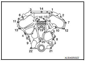
Exploded View
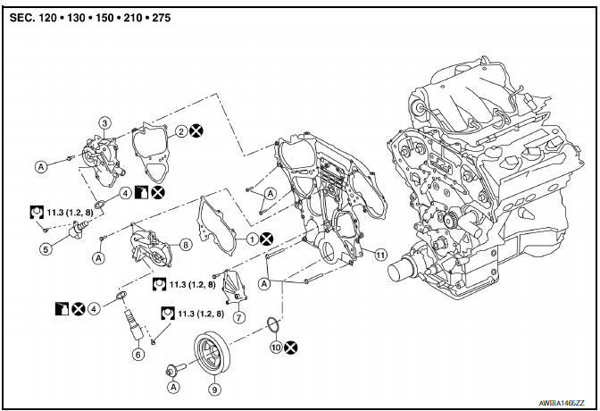
- Intake valve timing control solenoid valve cover gasket (LH)
- Intake valve timing control solenoid valve cover gasket (RH)
- Intake valve timing control solenoid valve cover (RH) (bank 1)
- O-ring 5. Intake valve timing control solenoid valve (RH) with O-ring
- Intake valve timing control solenoid valve (LH) with O-ring
- Water pump cover
- Intake valve timing control solenoid valve cover (LH) (bank 2)
- Crankshaft pulley
- Front oil seal
- Front timing chain case
- Refer to INSTALLATION
Removal and Installation
NOTE:
- This section describes the procedure for removal/installation of the front timing chain case without removing the oil pan (upper) from the vehicle.
- When rear timing chain case must be removed, remove the engine from the vehicle. Then remove front timing chain case, timing chain related parts, and rear timing chain case in this order, and install in reverse order of removal. Refer to EM-103, "Removal and Installation".
- Refer to EM-64, "Exploded View" for component parts location.
- When removing components such as hoses, tubes/lines, etc., cap or plug openings to prevent fluid from spilling.
REMOVAL
- Disconnect the battery negative terminal. Refer to PG-67, "Removal and Installation (Battery)".
- Remove engine under cover. Refer to EXT-15, "Exploded View".
- Drain the engine coolant from the radiator. Refer to CO-11, "Changing Engine Coolant".
- Drain the engine oil. Refer to LU-9, "Changing Engine Oil".
- Drain the power steering fluid. Refer to ST-12, "Draining".
- Remove engine room cover. Refer to EM-23, "Removal and Installation".
- Remove front air duct. Refer to EM-24, "Removal and Installation".
- Remove battery tray. Refer to PG-68, "Removal and Installation (Battery Tray)".
- Remove the hood ledge covers (RH and LH).
- Remove cowl top, cowl top extension and cowl top extension brace. Refer to EXT-21, "Removal and Installation".
- Remove upper radiator hose.
- Disconnect engine coolant reservoir hose from the radiator and remove engine coolant reservoir.
- Remove cooling fan assembly. Refer to CO-16, "Removal and Installation".
- Disconnect lower radiator hose from engine.
- Disconnect the power steering fluid reservoir tank hose from the power steering pump and fluid cooler and remove the power steering fluid reservoir tank. Refer to ST-29, "Exploded View".
- Remove the front (RH) wheel and tire using power tool. Refer to WT-60, "Adjustment".
- Remove front fender protector side cover (RH). Refer to EXT-24, "Removal and Installation".
- Remove the drive belt. Refer to EM-14, "Removal and Installation".
- Remove the rocker covers, if necessary. Refer to EM-48, "Removal and Installation (LH)" and EM-49, "Removal and Installation (RH)". NOTE: Necessary only when removing timing chains.
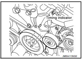
- If removing the timing chains, obtain compression TDC of No. 1 cylinder as follows:
- Rotate crankshaft pulley clockwise to align timing mark (grooved line without color) with timing indicator.
- Check that intake and exhaust camshaft lobes on No. 1 cylinder (right bank of engine) are located as shown.
- If not, turn the crankshaft one revolution (360) and align as shown.
- Lock the drive plate using Tool.
Tool number : - (J-50288)
CAUTION: Do not damage the ring gear teeth, or the signal plate teeth behind the ring gear, when setting the Tool.
- Remove the crankshaft pulley as follows:
- Loosen crankshaft pulley and locate bolt seating surface at 10 mm (0.39 in) from its original position.
- Position a pulley puller at recess hole of crankshaft pulley to remove crankshaft pulley.
CAUTION: Do not use a puller claw on the outer diameter of the crankshaft pulley.
- Remove the power steering pump. Refer to ST-28, "Removal and Installation".
- Remove the generator. Refer to CHG-28, "Removal and Installation".
- Remove the A/C compressor bolts, remove the A/C compressor and position aside. Refer to HA-37, "Removal and Installation for Compressor".
- Remove the generator bracket. Refer to CHG-28, "Exploded View".
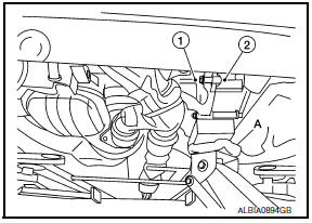
- Support the engine (1) and transaxle (2) using a suitable jack (A) as shown.
CAUTION:
- Position a suitable jack under the engine and transaxle assembly as shown.
- Do not damage the front exhaust tube or transaxle oil pan with the jack.
- Remove engine oil cooler tube bolts and bracket.
- Disconnect the oil pressure switch harness connector.
- Disconnect intake valve timing control solenoid valve harness connector.
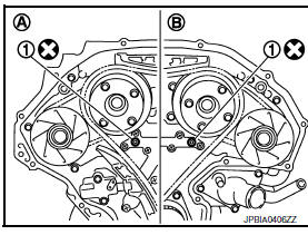
- Remove the intake valve timing control solenoid valve cover (RH) (bank 1) and intake valve timing control solenoid valve cover (LH) (bank 2).
- Loosen intake valve timing control solenoid valve cover bolts in the reverse order as shown.
CAUTION: The shaft in the intake valve timing control solenoid valve cover is inserted into the center hole of the intake camshaft sprocket. Remove the intake valve timing control solenoid valve cover by pulling straight out until the intake valve timing control solenoid valve cover disengages from the camshaft sprocket.
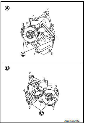
(A) : Intake valve timing control solenoid valve cover (RH) (bank 1)
(B)
: Intake valve timing control solenoid valve cover (LH) (bank 2)
(C) :
Dowel pin hole
- Shaft is engaged in intake camshaft sprocket center hole on inside. Pull straight out so as not to tilt until the shaft is disengaged.
- The mating surface of magnet retarder (2) may be fitted with the exhaust camshaft sprocket via engine oil. Open intake valve timing control solenoid valve cover (1) carefully.
- If the mating surface of the magnet retarder is fitted with the camshaft sprocket, open the intake valve timing control solenoid valve cover within the range that the load is not applied to the harness. Remove it so as to prevent magnet retarder from dropping.
CAUTION:
- Be careful not to damage magnet retarder.
- When carrying intake valve timing control solenoid valve cover, face the magnet retarder side up to prevent the intake valve timing control solenoid valve cover from falling from magnet retarder.
- Do not remove magnet retarder from intake valve timing control solenoid valve cover. (Disassembly prohibited)
- Remove the A/C idler pulley and bracket and the drive belt auto-tensioner.
- If necessary, remove the idler pulley and water pump cover.
- Remove lower oil pan. Refer to EM-36, "Removal and Installation (Lower Oil Pan)".
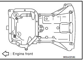
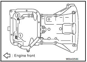
- Remove upper oil pan bolts (1) and (2) as shown. Refer to EM- 37, "Removal and Installation (Upper Oil Pan)".
- Remove the front timing chain case.
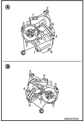
- Loosen the front timing chain case bolts in the order as shown.
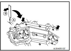
- Insert suitable tool into the notch (A) at the top of the front timing chain case as shown.
- Pry off the case by moving suitable tool (B) as shown.
- Cut liquid gasket for removal using Tool.
CAUTION:
- Do not use a screwdriver or similar tool.
- After removal, handle carefully so it does not bend, or warp under a load.
- Remove O-rings (1) from rear timing chain case.
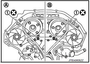
- Bank 1 (RH)
- Bank 2 (LH)
CAUTION:
- Use new O-rings for installation.
- Do not reuse O-rings.
- Remove the front oil seal from the front timing chain case using a suitable tool.
CAUTION: Do not damage the front cover.
- Remove all old Silicone RTV Sealant from all the bolt holes and bolts.
CAUTION: Do not damage the threads or mating surfaces.
- Use a scraper to remove all of the old Silicone RTV Sealant from the front timing chain case and opposite mating surfaces.
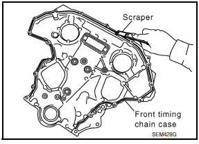
CAUTION: Do not damage the mating surfaces.
INSTALLATION
- Install dowel pins (right and left) into front timing chain case up to a point close to taper in order to shorten protrusion length.
NOTE: Be sure to place the dowel pins in original hole locations in the front timing chain case.
- Install the new front oil seal on the front timing chain case. Apply new engine oil to the oil seal edges.
NOTE: Install it so that each seal lip is oriented as shown.
- Install the new front oil seal so that it becomes flush with the face with front timing chain case using suitable tool.
CAUTION: Press fit straight and avoid causing burrs or tilting the oil seal.
NOTE: Make sure the garter spring is in position and seal lip is not inverted.
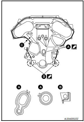
- Install new O-rings (1) on rear timing chain case
- Bank 1 (RH)
- Bank 2 (LH)
CAUTION:
- Use new O-rings for installation.
- Do not reuse O-rings.
- Apply Silicone RTV Sealant to front timing chain case as shown.
- Use Genuine Silicone RTV Sealant, or equivalent. Refer to GI- 21, "Recommended Chemical Products and Sealants".
- Before installation, wipe off the protruding sealant.
- C: 2.6 - 3.6 mm (0.102 - 0.142 in) dia.
CAUTION:
- Installation should be done within 5 minutes after applying liquid gasket.
- Do not fill the engine with oil for at least 30 minutes after the components are installed to allow the sealant to cure.
- Install dowel pin on the front timing chain case into dowel pin hole in rear timing chain case.
- Loosely install the front timing chain case bolts.
Bolt position Bolt diameter
1, 2 : 8 mm (0.31 in)
3 - 22 : 6 mm
(0.24 in)
- Tighten the front timing chain case bolts in the order as shown.
- Retighten the front timing chain case bolts in the order as shown.
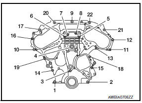
Bolt position Tightening specification
1, 2 : 28.5 N*m (2.9 kg-m, 21
ft-lb)
3 - 22 : 12.8 N*m (1.3 kg-m, 9 ft-lb)
- Install upper oil pan bolts (1) and (2) as shown. Refer to EM-37, "Removal and Installation (Upper Oil Pan)".
- Install lower oil pan. Refer to EM-36, "Removal and Installation (Lower Oil Pan)".
- Install intake valve timing control solenoid valve covers.
- Install new seal rings (1) in shaft grooves.
(A) : Intake valve timing control solenoid valve cover (LH) (bank 2)
CAUTION:
- When replacing seal rings, replace all rings with new ones on both intake valve timing control solenoid valve covers.
- Do not reuse O-rings.
- Check the joint between dowel pins and dowel pin holes for excessive free play.
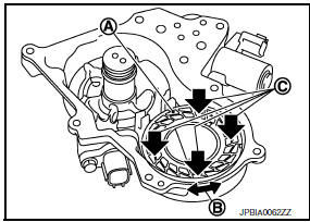
- (A): Mating surface of magnet retarder
- (B): Moves slightly
- (C): Not shaken
CAUTION: Always perform this procedure when removing to ensure the dowel pin holes are not worn or elongated.
- Being careful not to move seal ring from the installation groove, align the dowel pins on the front timing chain case with the holes to install valve timing control covers.
- Install intake valve timing control solenoid valve cover with a new gasket to front timing chain case.

- Intake valve timing control solenoid valve cover
- Magnet retard
CAUTION:
- Do not face magnet retarder side down to prevent magnet retarder from dropping.
- Check the mating surface of the magnet retarder and the drum of the exhaust camshaft sprocket for foreign materials.
- Align center of both shaft holes of the shaft and the intake camshaft sprocket, and then insert them.
- Be careful not to drop the seal ring from the shaft groove.
- When setting the intake valve timing control solenoid valve cover in position by hand, if intake valve timing control solenoid valve cover is not centered with the front timing chain case, the dowel pin of the magnet retarder may not be aligned with the dowel pin holes of the intake valve timing control solenoid valve cover. In this case, return to step "b".
- Tighten intake valve timing control solenoid valve cover bolts in the numerical order as shown.
Intake valve timing control solenoid valve cover bolts 11.3 N*m (1.2 kg-m, 8 ft-lb)
- Intake valve timing control solenoid valve cover (bank 1) (RH)
- Intake valve timing control solenoid valve cover (bank 2) (LH)
- Dowel pin hole
- Apply liquid gasket and install the water pump cover, if removed.
- Use Genuine Silicone RTV Sealant or equivalent. Refer to GI-21, "Recommended Chemical Products and Sealants".
CAUTION:
- Installation should be done within 5 minutes after applying liquid gasket.
- Do not fill the engine with oil for at least 30 minutes after the components are installed to allow the sealant to cure.
- Install crankshaft pulley and tighten the bolt in two steps.
- Lubricate thread and seat surface of the bolt with new engine oil.
- For the second step angle tighten using Tool.
Step 1 : 44.1 N*m (4.5 kg-m, 33 ft-lb)
Step 2 : 84 - 90 degrees
clockwise
Tool number : KV10112100 (BT-8653-A)
- Remove the Tool to unlock the driveplate
Tool number : - (J-50288)
CAUTION: Do not damage the ring gear teeth, or the signal plate teeth behind the ring gear, when removing the Tool.
- Rotate crankshaft pulley in normal direction (clockwise when viewed from front) to confirm it turns smoothly.
- Installation of the remaining components is in reverse order of removal.
INSPECTION AFTER INSTALLATION
- Before starting engine, check oil/fluid levels including engine coolant and engine oil. If less than required quantity, fill to the specified level. Refer to MA-15, "FOR USA AND CANADA : Fluids and Lubricants" (United States and Canada) or MA-16, "FOR MEXICO : Fluids and Lubricants" (Mexico).
- Use procedure below to check for fuel leakage.
- Turn ignition switch ON (with engine stopped). With fuel pressure applied to fuel piping, check for fuel leakage at connection points.
- Start engine. With engine speed increased, check again for fuel leakage at connection points.
- Run engine to check for unusual noise and vibration.
NOTE: If hydraulic pressure inside timing chain tensioner drops after removal and installation, slack in the guide may generate a pounding noise during and just after engine start. However, this is normal. Noise will stop after hydraulic pressure rises.
- Warm up engine thoroughly to make sure there is no leakage of fuel, exhaust gas, or any oils/fluids including engine oil and engine coolant.
- Bleed air from passages in lines and hoses, such as in cooling system.
- After cooling down engine, again check oil/fluid levels including engine oil and engine coolant. Refill to specified level, if necessary.
- Summary of the inspection items:
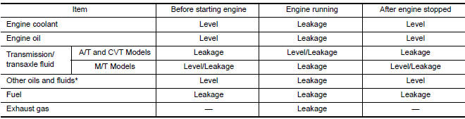
*Power steering fluid, brake fluid, etc.
 Intake Valve Timing Control
Exploded View
Intake valve timing control solenoid valve cover gasket (LH)
Intake valve timing control solenoid valve cover gasket (RH)
Intake valve timing control solenoid valve cover (RH) ...
 Timing Chain
Exploded View
Timing chain tensioner (secondary)
Internal chain guide
Timing chain tensioner (secondary)
Camshaft sprocket (EXH)
Timing chain (secondary)
Timing chain (primary)
C ...
Other materials:
Remote engine start operating range
CAUTION
When the Intelligent Key battery is discharged
or other strong radio wave
sources are present near the operating
location, the Intelligent Key operating
range becomes narrower, and the Intelligent
Key may not function properly.
The remote engine start function can only be
used when t ...
B2622 inside key antenna 2
Description
Detects whether Intelligent Key is inside the vehicle.
Installed under the center console.
DTC Logic
NOTE:
The Signal Tech II Tool (J-50190) can be used to perform the following
functions. Refer to the Signal Tech II
User Guide for additional information.
Check Intelli ...
B1209 - B1210 collision detection
Description
DTC B1209 - B1210 COLLISION DETECTION
The air bag diagnosis sensor unit will set this DTC if it has detected a
collision which has resulted in a frontalor side deployment of one or more
air bags or pre-tensioners. If this DTC is detected after a SRS repair, the air
bag diagnosis s ...
Nissan Maxima Owners Manual
- Illustrated table of contents
- Safety-Seats, seat belts and supplemental restraint system
- Instruments and controls
- Pre-driving checks and adjustments
- Monitor, climate, audio, phone and voice recognition systems
- Starting and driving
- In case of emergency
- Appearance and care
- Do-it-yourself
- Maintenance and schedules
- Technical and consumer information
Nissan Maxima Service and Repair Manual

0.0054