Nissan Maxima Service and Repair Manual: Intake Valve Timing Control
Exploded View
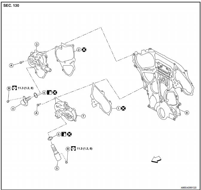
- Intake valve timing control solenoid valve cover gasket (LH)
- Intake valve timing control solenoid valve cover gasket (RH)
- Intake valve timing control solenoid valve cover (RH) (bank 1)
- Intake valve timing control solenoid valve (RH)
- Intake valve timing control solenoid valve (LH)
- O-ring
- Intake valve timing control solenoid valve cover (LH) (bank 2)
- Front timing chain case A. Refer to INSTALLATION B. Refer to
EM-54, "Removal and Installation".
 Engine
front
Engine
front
Intake Valve Timing Control Solenoid Valve (LH) (bank 2)
REMOVAL
- Remove hood ledge cover.
- Remove coolant reservoir and set aside.
- Disconnect intake valve timing control solenoid valve harness connector.
- Remove intake valve timing control solenoid valve cover (LH) (bank 2). Refer to EM-54, "Removal and Installation".
- Remove intake valve timing control solenoid valve and O-ring from intake valve timing control solenoid valve cover.
CAUTION: Do not reuse O-ring.
INSTALLATION
Installation is in the reverse order of removal.
CAUTION:
- Replace the O-ring for the intake valve timing control solenoid valve with a new one, then lubricate O-ring with engine oil before installing.
- Do not reuse O-ring.
Intake valve timing control solenoid valve bolt : 11.3 N*m (1.2 kg-m, 8 ft-lb)
Intake Valve Timing Control Solenoid Valve (RH) (bank 1)
REMOVAL
- Remove front fender protector side cover (RH). Refer to EXT-23, "Exploded View".
- Remove hood ledge cover.
- Remove coolant reservoir and set aside.
- Remove power steering reservoir and set aside.
- Support engine using suitable tool.
- Remove upper engine mount and bracket. Refer to EM-103, "Removal and Installation".
- Remove intake valve timing control solenoid valve cover bolt behind intake valve timing control solenoid valve. Refer to EM-54, "Removal and Installation".
- Disconnect intake valve timing control solenoid valve harness connector.
- Remove intake valve timing control solenoid valve and O-ring from intake valve timing control solenoid valve cover.
CAUTION: Do not reuse O-ring.
INSTALLATION
Installation is in the reverse order of removal.
CAUTION:
- Replace the O-ring for the intake valve timing control solenoid valve with a new one, then lubricate O-ring with engine oil before installing.
- Do not reuse O-rings.
Intake valve timing control solenoid valve bolt : 11.3 N*m (1.2 kg-m, 8 ft-lb)
 Rocker Cover
Exploded View
Camshaft position sensors (LH)
O-rings
Camshaft position sensors (RH)
O-rings
Rocker cover (RH)
Rocker cover gasket (RH)
Rocker cover gasket (LH)
Rocker cover (L ...
 Front Timing Chain Case
Exploded View
Intake valve timing control solenoid valve cover gasket (LH)
Intake valve timing control solenoid valve cover gasket (RH)
Intake valve timing control solenoid valve cover (RH) ...
Other materials:
Diagnosis and repair work flow
Work Flow
OVERALL SEQUENCE
DETAILED FLOW
1.GET INFORMATION FOR SYMPTOM
Get the detailed information from the customer about the symptom
(the condition and the environment
when the incident/malfunction occurred) using the "Diagnostic Work Sheet".
(Refer to EC-12, "Diagnostic ...
B2578, B2579 in-vehicle sensor
Description
In-vehicle Sensor
The in-vehicle sensor (1) is located on instrument lower cover
(LH).
It converts variations in compartment air temperature drawn from
the aspirator into a resistance value. It is then input into the A/C
auto amp.
In-vehicle Sensor Circuit
Aspira ...
Mode door control system
System Diagram
System Description
The mode door is automatically controlled by the temperature setting, ambient
temperature, in-vehicle temperature,
intake temperature and amount of sunload.
SYSTEM OPERATION
The A/C auto amp. receives data from each of the sensors.
The A/C auto amp. ...
Nissan Maxima Owners Manual
- Illustrated table of contents
- Safety-Seats, seat belts and supplemental restraint system
- Instruments and controls
- Pre-driving checks and adjustments
- Monitor, climate, audio, phone and voice recognition systems
- Starting and driving
- In case of emergency
- Appearance and care
- Do-it-yourself
- Maintenance and schedules
- Technical and consumer information
Nissan Maxima Service and Repair Manual

0.0105