Nissan Maxima Service and Repair Manual: Composite image signal circuit
Description
AV control unit transmits the playback DVD image signal and AUX image signal to the display unit.
Diagnosis Procedure
1.CHECK CONTINUITY COMPOSITE IMAGE SIGNAL CIRCUIT
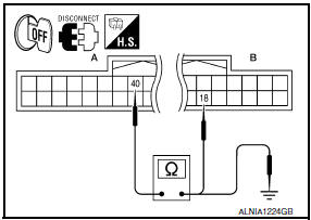
- Turn ignition switch OFF.
- Disconnect AV control unit connector M163 and display unit connector M142.
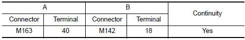
- Check continuity between AV control unit connector M163 (A) terminal 40 and display unit connector M142 (B) terminal 18.
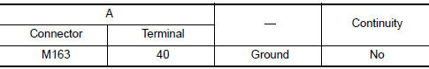
- Check continuity between AV control unit connector M163 (A) terminal 40 and ground.
2.CHECK AUX COMPOSITE SIGNAL
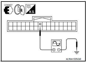
- Connect AV control unit connector M163 and display unit connector M142.
- Turn ignition switch ON.
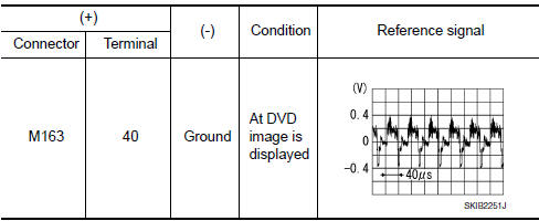
- Check signal between AV control unit harness connector M163 terminal 40 and ground.
 RGB digital image signal circuit
Description
Transmit the image displayed with AV control unit with RGB digital image
signal to the display unit.
Diagnosis Procedure
1.CHECK CONTINUITY RGB DIGITAL IMAGE SIGNAL CIRCUIT
Tu ...
 Aux image signal circuit
Description
Transmits the image signal of AUX device from auxiliary input jacks to
AV control unit.
AV control unit transmits the image signal that is input to the
display unit.
Diagnos ...
Other materials:
Rear view monitor system
System Diagram
System Description
When the shift selector is in the R position, the display shows a view to the
rear of the vehicle. Lines which indicate the vehicle clearance and distances
are also displayed.
Component Parts Location
Tweeter LH M51
Center speaker M130
Tweeter ...
Precaution
PRECAUTIONS
Precautions for Trouble Diagnosis
CAUTION:
Never apply 7.0 V or more to the measurement terminal.
Use a tester with open terminal voltage of 7.0 V or less.
Turn the ignition switch OFF and disconnect the battery cable from the
negative terminal when checking the harness.
P ...
Auto light system
System Diagram
System Description
BCM (Body Control Module) controls auto light operation according to
signals from optical sensor, lighting switch and ignition switch.
IPDM E/R (Intelligent Power Distribution Module Engine Room)
operates parking, license plate, tail, front fog lamps ...
Nissan Maxima Owners Manual
- Illustrated table of contents
- Safety-Seats, seat belts and supplemental restraint system
- Instruments and controls
- Pre-driving checks and adjustments
- Monitor, climate, audio, phone and voice recognition systems
- Starting and driving
- In case of emergency
- Appearance and care
- Do-it-yourself
- Maintenance and schedules
- Technical and consumer information
Nissan Maxima Service and Repair Manual

0.0062