Nissan Maxima Service and Repair Manual: B2555 stop lamp
Description
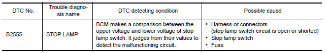
BCM detects the stop lamp status and confirms the stop lamp switch ON/OFF status. BCM confirms the engine start condition according to the stop lamp switch ON/OFF status.
DTC Logic
DTC DETECTION LOGIC
DTC CONFIRMATION PROCEDURE
1.PERFORM DTC CONFIRMATION PROCEDURE
-
Depress the brake pedal and wait for at least 1 second.
-
Check "Self Diagnostic Result" with CONSULT.
Diagnosis Procedure
Regarding Wiring Diagram information, refer to SEC-147, "Wiring Diagram" or SEC-128, "Wiring Diagram".
1.CHECK STOP LAMP SWITCH INPUT SIGNAL
-
Turn ignition switch OFF.
-
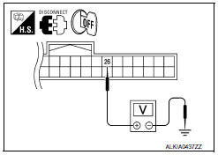
Disconnect BCM harness connector.
-
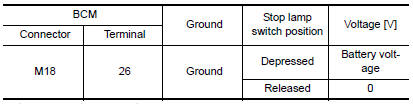
Check voltage between BCM harness connector M18 terminal 26 and ground.
2.CHECK STOP LAMP SWITCH POWER SUPPLY CIRCUIT
-
Disconnect stop lamp switch harness connector.
-
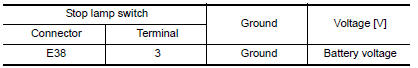
Check voltage between stop lamp harness connector E38 terminal 3 and ground.
3.CHECK STOP LAMP SWITCH CIRCUIT
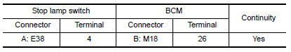
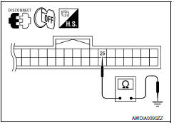
1. Check continuity between stop lamp switch harness connector E38 (A) terminal 4 and BCM harness connector M18 (B) terminal 26.
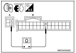
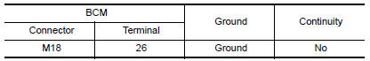
2. Check continuity between BCM harness connector M18 terminal 26 and ground.
4.CHECK STOP LAMP SWITCH
Refer to SEC-44, "Component Inspection".
5.CHECK INTERMITTENT INCIDENT
Refer to GI-41, "Intermittent Incident".
Inspection End.
Component Inspection
1.CHECK STOP LAMP SWITCH
-
Turn ignition switch OFF.
-
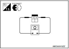
Disconnect stop lamp switch harness connector.
-
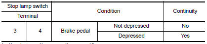
Check continuity between stop lamp switch terminals under the following conditions.
 B2193 chain of ECM-IMMU
Description
BCM performs the ID verification with ECM that allows the
engine to start. Start the engine if the ID is OK.
ECM prevents the engine from starting if the ID is not registered. BCM st ...
 B2556 push-button ignition switch
Description
The switch that changes the power supply position. BCM
maintains the power supply position status. BCM
changes the power supply position with the operation of the push-button ignition ...
Other materials:
Drive Belts
Checking Drive Belts
Idler pulley
Drive belt
Power steering oil pump
Drive belt auto-tensioner
Crankshaft pulley
Idler pulley
A/C compressor
Generator
Indicator
New drive belt range
Possible use range
View D
Engine front
WARNING: Inspect and check the dri ...
Washing
Wash dirt off with a wet sponge and plenty of
water. Clean the vehicle thoroughly using a mild
soap, a special vehicle soap or general purpose
dishwashing liquid mixed with clean, lukewarm
(never hot) water.
CAUTION
Do not use car washes that use acid in
the detergent. Some car washes, es ...
ECU diagnosis information
BCM (BODY CONTROL MODULE)
Reference Value
NOTE:
The Signal Tech II Tool (J-50190) can be used to perform the following
functions. Refer to the Signal Tech II
User Guide for additional information.
Activate and display TPMS transmitter IDs
Display tire pressure reported by the TPMS tran ...
Nissan Maxima Owners Manual
- Illustrated table of contents
- Safety-Seats, seat belts and supplemental restraint system
- Instruments and controls
- Pre-driving checks and adjustments
- Monitor, climate, audio, phone and voice recognition systems
- Starting and driving
- In case of emergency
- Appearance and care
- Do-it-yourself
- Maintenance and schedules
- Technical and consumer information
Nissan Maxima Service and Repair Manual

0.0064