Nissan Maxima Service and Repair Manual: B2556 push-button ignition switch
Description
The switch that changes the power supply position. BCM maintains the power supply position status. BCM changes the power supply position with the operation of the push-button ignition switch.
DTC Logic
DTC DETECTION LOGIC
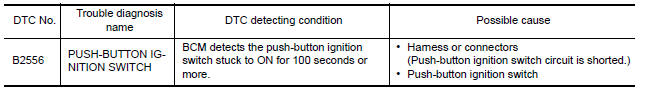
DTC CONFIRMATION PROCEDURE
1.PERFORM DTC CONFIRMATION PROCEDURE
-
Start the engine and wait for at least 100 seconds.
-
Check "Self Diagnostic Result" with CONSULT.
Diagnosis Procedure
Regarding Wiring Diagram information, refer to SEC-147, "Wiring Diagram" or SEC-128, "Wiring Diagram".
1.CHECK PUSH-BUTTON IGNITION SWITCH INPUT SIGNAL
-
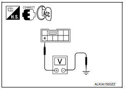
Turn ignition switch OFF.
-
Disconnect push-button ignition switch harness connector.
-
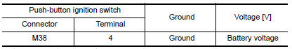
Check voltage between push-button ignition switch harness connector M38 terminal 4 and ground.
2.CHECK PUSH-BUTTON IGNITION SWITCH
Refer to SEC-47, "Component Inspection".
3.CHECK INTERMITTENT INCIDENT
Refer to GI-41, "Intermittent Incident".
Inspection End.
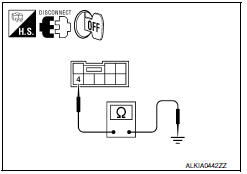
4.CHECK PUSH-BUTTON IGNITION SWITCH CIRCUIT FOR SHORT
-
Disconnect BCM harness connector and IPDM E/R harness connector.
-
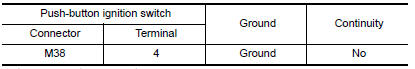
Check continuity between push-button ignition switch harness connector M38 terminal 4 and ground.
Component Inspection
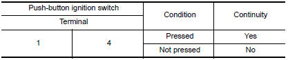
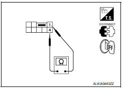
1.CHECK PUSH-BUTTON IGNITION SWITCH
-
Turn ignition switch OFF.
-
Disconnect push-button ignition switch harness connector.
-
Check continuity between push-button ignition switch terminals under the following conditions.
 B2555 stop lamp
Description
BCM detects the stop lamp status and confirms the stop
lamp switch ON/OFF status. BCM confirms the
engine start condition according to the stop lamp switch ON/OFF status.
DTC Logic
...
 B2557 vehicle speed
Description
BCM receives the 2 vehicle speed signals via CAN
communication. One signal is transmitted by the "combination
meter". Another signal is transmitted by "ABS actuator and electric unit ...
Other materials:
Control valve
Exploded View
Transaxle assembly
Control valve
Snap ring
Collar
Manual plate
Lock nut
Lock nut
Oil pan bolt
O-ring
Drain plug
Oil pan
...
Basic inspection
DIAGNOSIS AND REPAIR WORKFLOW
Work Flow (With GR8-1200 NI)
STARTING SYSTEM DIAGNOSIS WITH GR8-1200 NI
To test the starting system, use the following special service tool:
GR8-1200 NI Multitasking battery and electrical diagnostic station
NOTE: Refer to the diagnostic station
Instru ...
ABS branch line circuit
Diagnosis Procedure
1.CHECK CONNECTOR
Turn the ignition switch OFF.
Disconnect the battery cable from the negative terminal.
Check the terminals and connectors of the ABS actuator and
electric unit (control unit) for damage, bend
and loose connection (unit side and connector side).
...
Nissan Maxima Owners Manual
- Illustrated table of contents
- Safety-Seats, seat belts and supplemental restraint system
- Instruments and controls
- Pre-driving checks and adjustments
- Monitor, climate, audio, phone and voice recognition systems
- Starting and driving
- In case of emergency
- Appearance and care
- Do-it-yourself
- Maintenance and schedules
- Technical and consumer information
Nissan Maxima Service and Repair Manual

0.0079