Nissan Maxima Service and Repair Manual: P1211 TCS control unit
Description
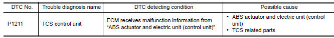
The malfunction information related to TCS is transferred via the CAN communication line from "ABS actuator and electric unit (control unit)" to ECM.
Be sure to erase the malfunction information such as DTC not only for "ABS actuator and electric unit (control unit)" but also for ECM after TCS related repair.
DTC Logic
DTC DETECTION LOGIC
Freeze frame data is not stored in the ECM for this self-diagnosis.
DTC CONFIRMATION PROCEDURE
1.PRECONDITIONING
TESTING CONDITION: Before performing the following procedure, confirm that battery voltage is more than 10.5 V at idle.
2.PERFORM DTC CONFIRMATION PROCEDURE
- Start engine and let it idle for at least 60 seconds.
- Check 1st trip DTC.
 P1148, P1168 closed loop control
DTC Logic
DTC DETECTION LOGIC
NOTE:
DTC P1148 or P1168 is displayed with another DTC for A/F sensor 1.
Perform the trouble diagnosis for the corresponding DTC.
...
 P1212 TCS communication line
Description
This CAN communication line is used to control the smooth engine operation
during the TCS operation. Pulse
signals are exchanged between ECM and "ABS actuator and electric unit (contr ...
Other materials:
Bluetooth control unit
Reference Values
TERMINAL LAYOUT
PHYSICAL VALUES
...
Blocking wheels
A. Blocks
B. Flat tire
Place suitable blocks at both the front and back
of the wheel diagonally opposite the flat tire to
prevent the vehicle from moving when it is jacked
up.
WARNING
Be sure to block the wheel as the vehicle
may move and result in personal injury.
Getting the spare tir ...
System Description
NOISE, VIBRATION, AND HARSHNESS (NVH) TROUBLESHOOTING
NVH Troubleshooting - Engine Noise
Camshaft bearing noise
Piston pin noise
Piston slap noise
Main bearing noise
Connecting rod bearing noise
Drive belt noise (Sticking/Slipping)
Drive belt noise (Slipping)
Water pump n ...
Nissan Maxima Owners Manual
- Illustrated table of contents
- Safety-Seats, seat belts and supplemental restraint system
- Instruments and controls
- Pre-driving checks and adjustments
- Monitor, climate, audio, phone and voice recognition systems
- Starting and driving
- In case of emergency
- Appearance and care
- Do-it-yourself
- Maintenance and schedules
- Technical and consumer information
Nissan Maxima Service and Repair Manual

0.0055