Nissan Maxima Service and Repair Manual: Telescopic motor
Description
- The telescopic motor is installed to the steering column assembly.
- The telescopic motor is activated with the automatic drive positioner control unit.
- Compresses the steering column by changing the rotation direction of telescopic motor.
Component Function Check
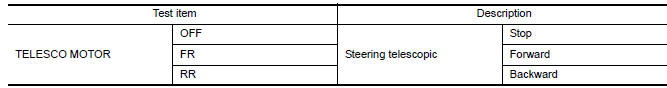
1.CHECK FUNCTION
- Select "TELESCO MOTOR" in "ACTIVE TEST" mode with CONSULT.
- Check the telescopic motor operation
Diagnosis Procedure
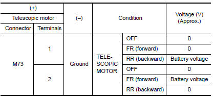
1. CHECK TELESCOPIC MOTOR POWER SUPPLY
- Turn ignition switch OFF.
- Disconnect tilt motor.
- Turn the ignition switch ON.
- Perform "ACTIVE TEST" ("TELESCO MOTOR") with CONSULT.
- Check voltage between telescopic motor harness connector and ground.
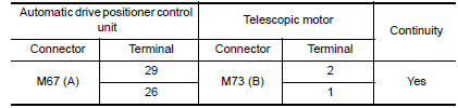
2.CHECK TELESCOPIC MOTOR
- Turn ignition switch OFF.
- Disconnect automatic drive positioner control unit.
- Check continuity between automatic drive positioner control unit harness connector and telescopic motor harness connector.
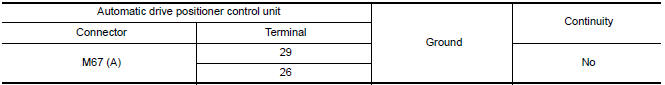
- Check continuity between automatic drive positioner control unit harness connector and ground.
 Tilt motor
Description
The tilt motor is installed to the steering column assembly.
The tilt motor is activated with the automatic drive positioner control
unit.
The steering column is tilted upward/d ...
 Door mirror motor
Description
It makes mirror face operate from side to side and up and down with the
electric power that automatic drive positioner control unit supplies.
Component Function Chec
1. CHECK DOOR MIR ...
Other materials:
Precaution
Precaution for Supplemental Restraint System (SRS) "AIR BAG" and "SEAT
BELT
PRE-TENSIONER"
The Supplemental Restraint System such as "AIR BAG" and "SEAT BELT PRE-TENSIONER",
used along
with a front seat belt, helps to reduce the risk or severity of injury to the
driver ...
Intelligent key interlock function
INTELLIGENT KEY INTERLOCK FUNCTION : System
INTELLIGENT KEY INTERLOCK FUNCTION : System Description
OUTLINE
When unlocking doors by using Intelligent Key or door request switch (driver
side), seat slide and steering tilt move directly to the exit assist
function.
Other loads move to the ...
Spark Plug
Exploded View
Ignition coil
Spark plug
Rocker cover (RH)
Rocker cover (LH)
Removal and Installation
REMOVAL
Remove the ignition coil. Refer to EM-42, "Removal and
Installation (LH)" and EM-42, "Removal and Installation (RH)".
Remove the spark plug with a suitable spark p ...
Nissan Maxima Owners Manual
- Illustrated table of contents
- Safety-Seats, seat belts and supplemental restraint system
- Instruments and controls
- Pre-driving checks and adjustments
- Monitor, climate, audio, phone and voice recognition systems
- Starting and driving
- In case of emergency
- Appearance and care
- Do-it-yourself
- Maintenance and schedules
- Technical and consumer information
Nissan Maxima Service and Repair Manual

0.0048