Nissan Maxima Service and Repair Manual: Tilt motor
Description
- The tilt motor is installed to the steering column assembly.
- The tilt motor is activated with the automatic drive positioner control unit.
- The steering column is tilted upward/downward by changing the rotation direction of tilt motor.
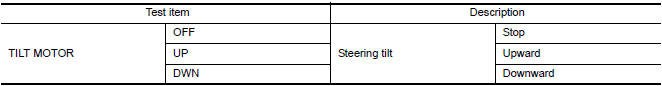
Component Function Check
1. CHECK FUNCTION
- Select "TILT MOTOR" in "ACTIVE TEST" mode with CONSULT.
- Check the tilt motor operation.
Diagnosis Procedure
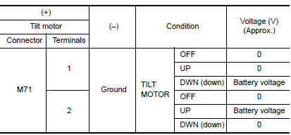
1. CHECK TILT MOTOR POWER SUPPLY
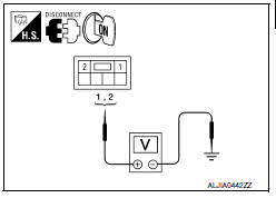
- Turn ignition switch OFF.
- Disconnect tilt motor.
- Turn the ignition switch ON.
- Perform "ACTIVE TEST" ("TILT MOTOR") with CONSULT.
- Check voltage between tilt motor harness connector and ground.
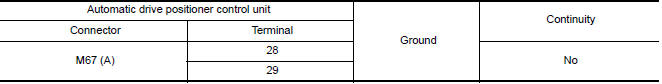
2. CHECK TILT MOTOR CIRCUIT
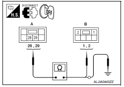
- Turn ignition switch OFF.
- Disconnect automatic drive positioner control unit.
- Check continuity between automatic drive positioner control unit harness connector and tilt motor harness connecto
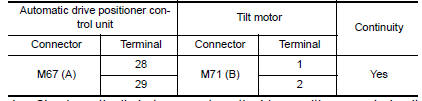
- Check continuity between automatic drive positioner control unit harness connector and ground.
 Lifting motor (rear)
Description
The lifting motor (rear) is installed to the seat frame.
The lifting motor (rear) is activated with the driver seat control
unit.
The seat lifter (rear) is moved upward/downward ...
 Telescopic motor
Description
The telescopic motor is installed to the steering column assembly.
The telescopic motor is activated with the automatic drive
positioner control unit.
Compresses the steering co ...
Other materials:
Electronic controlled engine mount
Description
In the idle range, ECM turns OFF the electronically-controlled engine mount
control solenoid valve and applies
manifold pressure to the electronically controlled engine mount. This decreases
damping force of the electronically-
controlled engine mount and absorbs vibrations trav ...
Telescopic switch
Description
ADP steering switch (telescopic switch) is equipped to the steering column.
The operation signal is input to the automatic drive positioner control unit
when the telescopic switch is operated.
Component Function Check
1. CHECK FUNCTION
Select "TELESCO SW-FR", "TELESCO SW-RR" i ...
Door mirror remote control switch
CHANGEOVER SWITCH
CHANGEOVER SWITCH : Description
Changeover switch is integrated into door mirror remote control switch.
Changeover switch has three positions (L, N and R).
It changes door mirror
motor operation by transmitting control signal to automatic drive positioner
control unit.
C ...
Nissan Maxima Owners Manual
- Illustrated table of contents
- Safety-Seats, seat belts and supplemental restraint system
- Instruments and controls
- Pre-driving checks and adjustments
- Monitor, climate, audio, phone and voice recognition systems
- Starting and driving
- In case of emergency
- Appearance and care
- Do-it-yourself
- Maintenance and schedules
- Technical and consumer information
Nissan Maxima Service and Repair Manual

0.0054