Nissan Maxima Service and Repair Manual: Lifting motor (rear)
Description
- The lifting motor (rear) is installed to the seat frame.
- The lifting motor (rear) is activated with the driver seat control unit.
- The seat lifter (rear) is moved upward/downward by changing the rotation direction of lifting motor (rear).
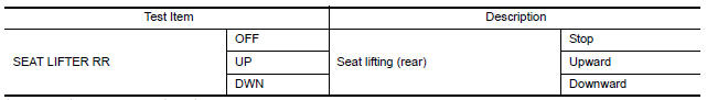
Component Function Check
1. CHECK FUNCTION
- Select "SEAT LIFTER RR" in "ACTIVE TEST" mode with CONSULT.
- Check the lifting motor (rear) operation.
Diagnosis Procedure
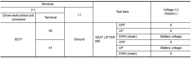
1. CHECK LIFTING MOTOR (REAR) POWER SUPPLY
- Turn the ignition switch to ACC.
- Perform "ACTIVE TEST" ("SEAT LIFTER RR") with CONSULT.
- Check voltage between driver seat control unit harness connector and ground.
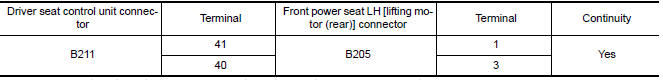
2. CHECK LIFTING MOTOR (REAR) CIRCUIT
- Turn ignition switch OFF.
- Disconnect driver seat control unit and front power seat LH [lifting motor (rear)].
- Check continuity between driver seat control unit harness connector and front power seat LH [lifting motor (rear)] harness connecto
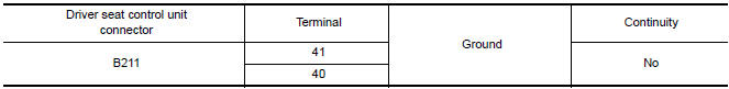
- Check continuity between driver seat control unit harness connector and ground.
3. CHECK INTERMITTENT INCID
 Lifting motor (front)
Description
The lifting motor (front) is installed to the seat frame.
The lifting motor (front) is activated with the driver seat
control unit.
The lifter (front) is moved upward/downward b ...
 Tilt motor
Description
The tilt motor is installed to the steering column assembly.
The tilt motor is activated with the automatic drive positioner control
unit.
The steering column is tilted upward/d ...
Other materials:
Shift control system
System Diagram
NOTE: The gear ratio is set for each position separately.
System Description
In order to select the gear ratio that can obtain the driving force in
accordance with driver's intention and the
vehicle condition, TCM monitors the driving conditions, such as the vehicle
speed a ...
B2556 push-button ignition switch
Description
The switch that changes the power supply position. BCM
maintains the power supply position status. BCM
changes the power supply position with the operation of the push-button ignition
switch.
DTC Logic
DTC DETECTION LOGIC
DTC CONFIRMATION PROCEDURE
1.PERFORM DTC CONFIRMATION ...
Precaution
Precaution for Supplemental Restraint System (SRS) "AIR BAG" and
"SEAT BELT PRE-TENSIONER"
The Supplemental Restraint System such as "AIR BAG" and "SEAT BELT
PRE-TENSIONER", used along with a front seat belt, helps to reduce the risk
or severity of injury to the driver and front passenger for ...
Nissan Maxima Owners Manual
- Illustrated table of contents
- Safety-Seats, seat belts and supplemental restraint system
- Instruments and controls
- Pre-driving checks and adjustments
- Monitor, climate, audio, phone and voice recognition systems
- Starting and driving
- In case of emergency
- Appearance and care
- Do-it-yourself
- Maintenance and schedules
- Technical and consumer information
Nissan Maxima Service and Repair Manual

0.0075