Nissan Maxima Service and Repair Manual: Lifting motor (front)
Description
- The lifting motor (front) is installed to the seat frame.
- The lifting motor (front) is activated with the driver seat control unit.
- The lifter (front) is moved upward/downward by changing the rotation direction of lifting motor (front).
Component Function Check
1. CHECK FUNCTION
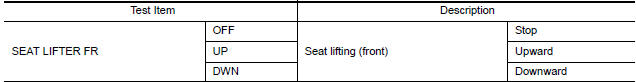
- Select "SEAT LIFTER FR" in "ACTIVE TEST" mode with CONSULT.
- Check the lifting motor (front) operation.
Diagnosis Procedure
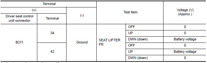
1. CHECK LIFTING MOTOR (FRONT) POWER SUPPLY
- Turn the ignition switch to ACC.
- Perform "ACTIVE TEST" ("SEAT LIFTER FR") with CONSULT.
- Check voltage between driver seat control unit harness connector and ground.
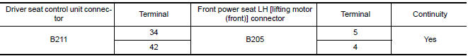
2. CHECK LIFTING MOTOR (FRONT) CIRCUIT
- Turn ignition switch OFF.
- Disconnect driver seat control unit and front power seat LH [lifting motor (front)].
- Check continuity between driver seat control unit harness connector and front power seat LH [lifting motor (front)] harness connector.
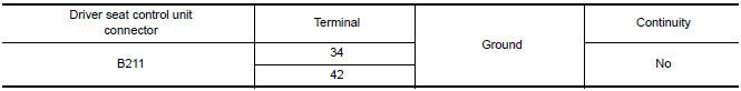
- Check continuity between driver seat control unit harness connector and ground.
3. CHECK INTERMITTENT INCIDENT
 Reclining motor
Description
The reclining motor is installed to the seatback assembly.
The reclining motor is activated with the driver seat control unit.
The seatback is reclined forward/backward by changing ...
 Lifting motor (rear)
Description
The lifting motor (rear) is installed to the seat frame.
The lifting motor (rear) is activated with the driver seat control
unit.
The seat lifter (rear) is moved upward/downward ...
Other materials:
P0507 ISC system
Description
The ECM controls the engine idle speed to a specified level via the fine
adjustment of the air, which is let into
the intake manifold, by operating the electric throttle control actuator. The
operating of the throttle valve is varied
to allow for optimum control of the engine id ...
Servicing air conditioner
The air conditioner system in your NISSAN vehicle
is charged with a refrigerant designed with
the environment in mind.
This refrigerant does not harm the earth's
ozone layer.
Special charging equipment and lubricant is required
when servicing your NISSAN air conditioner.
Using improper refr ...
Subwoofer
Removal and Installation
Subwoofer (LH)
Subwoofer (RH)
Subwoofer screws
Subwoofer connectors
REMOVAL
Remove the rear parcel shelf finisher. Refer to INT-28, "Removal
and Installation".
Remove the subwoofer screws.
Pull out the subwoofer, disconnect the h ...
Nissan Maxima Owners Manual
- Illustrated table of contents
- Safety-Seats, seat belts and supplemental restraint system
- Instruments and controls
- Pre-driving checks and adjustments
- Monitor, climate, audio, phone and voice recognition systems
- Starting and driving
- In case of emergency
- Appearance and care
- Do-it-yourself
- Maintenance and schedules
- Technical and consumer information
Nissan Maxima Service and Repair Manual

0.0054