Nissan Maxima Service and Repair Manual: Reclining motor
Description
- The reclining motor is installed to the seatback assembly.
- The reclining motor is activated with the driver seat control unit.
- The seatback is reclined forward/backward by changing the rotation direction of reclining motor.
Component Function Check
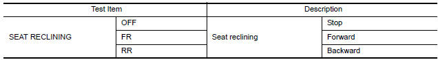
1. CHECK FUNCTION
- Select "SEAT RECLINING" in "ACTIVE TEST" mode with CONSULT.
- Check the reclining motor LH operation.
Diagnosis Procedure
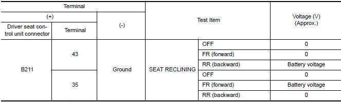
1. CHECK RECLINING MOTOR POWER SUPPLY
- Turn the ignition switch to ACC.
- Perform "ACTIVE TEST" ("SEAT RECLINING") with CONSULT.
- Check voltage between driver seat control unit harness connector and ground.
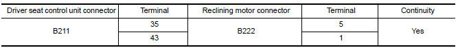
2. CHECK RECLINING MOTOR CIRCUIT
- Turn ignition switch OFF.
- Disconnect driver seat control unit and reclining motor.
- Check continuity between driver seat control unit harness connector and reclining motor harness connector.
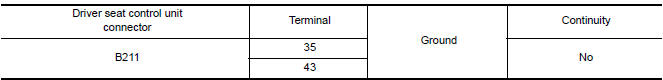
- Check continuity between driver seat control unit harness connector and ground.
3. CHECK INTERMITTENT INCIDENT
 Sliding motor
Description
The sliding motor LH is installed to the seat frame.
The sliding motor LH is activated with the driver seat control unit.
The seat is slid forward/backward by changing the rotation ...
 Lifting motor (front)
Description
The lifting motor (front) is installed to the seat frame.
The lifting motor (front) is activated with the driver seat
control unit.
The lifter (front) is moved upward/downward b ...
Other materials:
CVT fluid cooler system
Cleaning
Whenever an automatic transaxle is repaired, overhauled,
or replaced, the CVT fluid cooler mounted in the
radiator must be inspected and cleaned.
Metal debris and friction material, if present, can be trapped or be deposited
in the CVT fluid cooler. This
debris can contaminate t ...
Diagnosis and repair workflow
Work Flow
OVERALL SEQUENCE
DETAILED FLOW
1.CHECK SYMPTOM
Check the malfunction symptoms by performing the following items.
Interview the customer to obtain the malfunction information
(conditions and environment when the malfunction occurred).
Check the symptom.
2.SELF-DIAGNOSIS (C ...
ECU diagnosis information
BCM (BODY CONTROL MODULE)
Reference Value
NOTE: The Signal Tech II Tool (J-50190) can be used
to perform the following functions. Refer to the Signal Tech II User Guide
for additional information.
Activate and display TPMS transmitter IDs
Display tire pressure reported by the ...
Nissan Maxima Owners Manual
- Illustrated table of contents
- Safety-Seats, seat belts and supplemental restraint system
- Instruments and controls
- Pre-driving checks and adjustments
- Monitor, climate, audio, phone and voice recognition systems
- Starting and driving
- In case of emergency
- Appearance and care
- Do-it-yourself
- Maintenance and schedules
- Technical and consumer information
Nissan Maxima Service and Repair Manual

0.0053