Nissan Maxima Owners Manual: BSW driving situations
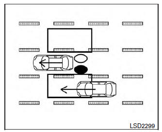
Illustration 1 - Approaching from behind
Indicator
on 
Indicator
off 
Indicator
flashing 
Another vehicle approaching from behind
Illustration 1: The side BSW/RCTA indicator light illuminates if a vehicle enters the detection zone from behind in an adjacent lane.
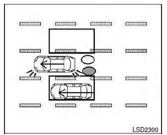
Illustration 2 - Approaching from behind
Illustration 2: If the driver activates the turn signal when another vehicle is in the detection zone, then the system chimes (twice) and the side indicator light flashes.
NOTE:
The radar sensors may not detect vehicles which are approaching rapidly from behind.
If the driver activates the turn signal before a vehicle enters the detection zone, the side indicator light will flash but no chime will sound when the other vehicle is detected.
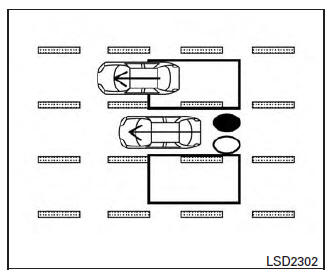
Illustration 3 - Overtaking another vehicle
Overtaking another vehicle
Illustration 3: The side indicator light illuminates if you overtake a vehicle and that vehicle stays in the detection zone for approximately 2 seconds.
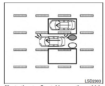
Illustration 4 - Overtaking another vehicle
Illustration 4: If the driver activates the turn signal while another vehicle is in the detection zone, then the system chimes (twice) and the side indicator light flashes.
NOTE:
- When overtaking several vehicles in a row, the vehicles after the first vehicle may not be detected if they are traveling close together
- The radar sensors may not detect slower moving vehicles if they are passed quickly.
- If the driver activates the turn signal before a vehicle enters the detection zone, the side indicator light will flash but no chime will sound when the other vehicle is detected. .
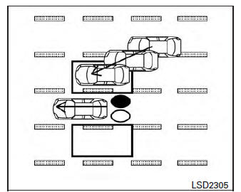
Illustration 5 - Entering from the side
Entering from the side
Illustration 5: The side indicator light illuminates if a vehicle enters the detection zone from either side.
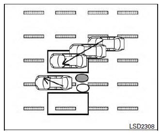
Illustration 6 - Entering from the side
Illustration 6: If the driver activates the turn signal while another vehicle is in the detection zone, then the system chimes (twice) and the side indicator light flashes.
NOTE:
- If the driver activates the turn signal before a vehicle enters the detection zone, the side indicator light will flash but no chime will sound when the other vehicle is detected.
- The radar sensors may not detect a vehicle which is traveling at about the same speed as your vehicle when it enters the detection zone.
 BSW system limitations
WARNING
Listed below are the system limitations for
the BSW system. Failure to operate the
vehicle in accordance with these system
limitations could result in serious injury or
death.
The BSW sy ...
 System temporarily unavailable
When radar blockage is detected, the system will
be deactivated automatically. The "Side Radar
Obstruction" warning message will appear and
the BSW/RCTA indicator (white) will blink A in
the v ...
Other materials:
P0127 IAT sensor
Description
The intake air temperature sensor is built-into the mass air flow sensor
(1). The sensor detects intake air temperature and transmits a
signal to the ECM.
The temperature sensing unit uses a thermistor which is sensitive to
the change in temperature. Electrical resistance o ...
Center speaker
Description
The AV control unit sends audio signals to the BOSE speaker amp. The BOSE
speaker amp. amplifies the
audio signals before sending them to the center speaker using the audio signal
circuits.
Diagnosis Procedure
1.CONNECTOR CHECK
Check the AV control unit, BOSE speaker amp. and s ...
Instrument lower panel LH
Removal and Installation
REMOVAL
Using a suitable tool, gently remove the instrument side finisher
(LH) (1).
Remove the instrument lower panel (LH) (1).
Open the fuse block cover and remove the instrument lower panel screw
(A).
Disconnect the harness connectors and aspirator ...
Nissan Maxima Owners Manual
- Illustrated table of contents
- Safety-Seats, seat belts and supplemental restraint system
- Instruments and controls
- Pre-driving checks and adjustments
- Monitor, climate, audio, phone and voice recognition systems
- Starting and driving
- In case of emergency
- Appearance and care
- Do-it-yourself
- Maintenance and schedules
- Technical and consumer information
Nissan Maxima Service and Repair Manual

0.0063