Nissan Maxima Owners Manual: System temporarily unavailable
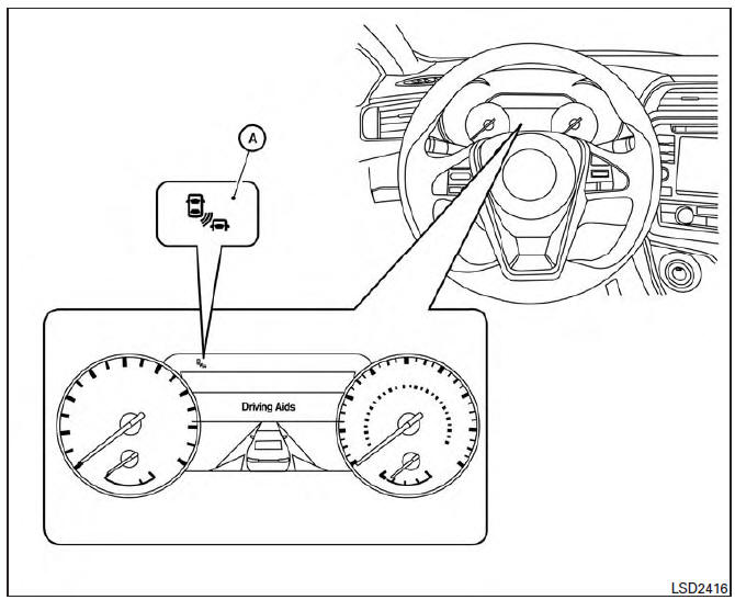
When radar blockage is detected, the system will be deactivated automatically. The "Side Radar Obstruction" warning message will appear and the BSW/RCTA indicator (white) will blink A in the vehicle information display.
The system is not available until the conditions no longer exist.
The radar sensors may be blocked by temporary ambient conditions such as splashing water, mist or fog. The blocked condition may also be caused by objects such as ice, frost or dirt obstructing the radar sensors.
NOTE:
If the BSW system stops working, the RCTA system (if so equipped) will also stop working. Action to take:
When the above conditions no longer exist, the system will resume automatically.
Malfunction
If the BSW system malfunctions, it will turn off automatically. The system malfunction warning message with the BSW/RCTA indicator (orange) will appear in the vehicle information display.
NOTE:
If the BSW system stops working, the RCTA system (if so equipped) will also stop working.
Action to take:
Stop the vehicle in a safe location, place the vehicle in the P (Park) position, turn the engine off and restart the engine. If the message continues to appear, have the system checked. It is recommended that you visit a NISSAN dealer for this service.
 BSW driving situations
Illustration 1 - Approaching from behind
Indicator
on
Indicator
off
Indicator
flashing
Another vehicle approaching from
behind
Illustration 1: The side BSW/RCTA indicator
light illumi ...
 System maintenance
The two radar sensors 1 for the BSW and
RCTA systems are located near the rear bumper.
Always keep the area near the radar sensors
clean.
The radar sensors may be blocked by temporary
amb ...
Other materials:
A-bag branch line circuit
Diagnosis Procedure
WARNING:
Always observe the following items for preventing accidental
activation.
- Before servicing, turn ignition switch OFF, disconnect battery negative
terminal, and wait 3 minutes
or more. (To discharge backup capacitor.)
- Never use unspecified tester or other ...
Power supply and ground circuit
BCM
BCM : Diagnosis Procedure
1. CHECK FUSE AND FUSIBLE LINK
Check if the following BCM fuses or fusible link are blown.
2. CHECK POWER SUPPLY CIRCUIT
Turn ignition switch OFF.
Disconnect BCM.
Check voltage between BCM harness connector and ground.
3. CHECK GROUND CIRCUIT
Che ...
U1310 AV control unit
Description
Part name
Description
AV CONTROL UNIT
It is the master unit of the MULTI AV system and it is connected
to each control unit by means of communication. It operates each
system according to communication signals from the AV contro ...
Nissan Maxima Owners Manual
- Illustrated table of contents
- Safety-Seats, seat belts and supplemental restraint system
- Instruments and controls
- Pre-driving checks and adjustments
- Monitor, climate, audio, phone and voice recognition systems
- Starting and driving
- In case of emergency
- Appearance and care
- Do-it-yourself
- Maintenance and schedules
- Technical and consumer information
Nissan Maxima Service and Repair Manual

0.0052