Nissan Maxima Owners Manual: Blind Spot Warning (BSW) (if so equipped)
WARNING
Failure to follow the warnings and instructions for proper use of the BSW system could result in serious injury or death.
- The BSW system is not a replacement for proper driving procedures and is not designed to prevent contact with vehicles or objects. When changing lanes, always use the side and rear mirrors and turn and look in the direction your vehicle will move to ensure it is safe to change lanes. Never rely solely on the BSW system.
The BSW system helps alert the driver of other vehicles in adjacent lanes when changing lanes.
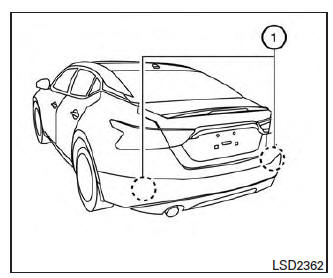
The BSW system uses radar sensors 1 installed near the rear bumper to detect other vehicles in an adjacent lane.
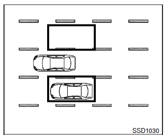
Detection zone
The radar sensors can detect vehicles on either side of your vehicle within the detection zone shown as illustrated. This detection zone starts from the outside mirror of your vehicle and extends approximately 10 ft (3.0 m) behind the rear bumper, and approximately 10 ft (3.0 m) sideways.
- BSW system operation
- How to enable/disable the BSW system
- BSW system limitations
- BSW driving situations
- System temporarily unavailable
- System maintenance
 Drive mode selector
Drive mode selector switches
Two driving modes can be selected by using the
drive mode selector switches, NORMAL and
SPORT.
NOTE:
When the drive mode select switch selects a
mode, the mo ...
 BSW system operation
1. Side BSW/RCTA Indicator Light
2. BSW/RCTA Indicator
The BSW system operates above approximately
20 mph (32km/h).
If the radar sensors detect a vehicle in the detection
zone, the side BSW ...
Other materials:
The braking distance is long
Diagnosis Procedure
CAUTION:
The stopping distance on slippery road surfaces might be longer with the ABS
operating than when
the ABS is not operating.
1.CHECK FUNCTION
Turn ignition switch OFF and disconnect ABS actuator and electric unit
(control unit) connector to deactivate
ABS. In ...
HomeLink Universal Transceiver
The HomeLink Universal Transceiver provides
a convenient way to consolidate the functions of
up to three individual hand-held transmitters into
one built-in device.
HomeLink Universal Transceiver:
Will operate most radio frequency devices
such as garage doors, gates, home and office
li ...
Startup display
When the vehicle in placed in the ON or ACC
position the screens that display in the vehicle
information display include:
Home
Audio
Navigation
Drive Computer
Fuel economy
Driving Aids (if so equipped)
Tire Pressures
Chassis Control (if so equipped)
SPORT
Warning Review
Set ...
Nissan Maxima Owners Manual
- Illustrated table of contents
- Safety-Seats, seat belts and supplemental restraint system
- Instruments and controls
- Pre-driving checks and adjustments
- Monitor, climate, audio, phone and voice recognition systems
- Starting and driving
- In case of emergency
- Appearance and care
- Do-it-yourself
- Maintenance and schedules
- Technical and consumer information
Nissan Maxima Service and Repair Manual

0.0068