Nissan Maxima Owners Manual: System maintenance
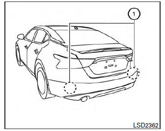
The two radar sensors 1 for the BSW and RCTA systems are located near the rear bumper.
Always keep the area near the radar sensors clean.
The radar sensors may be blocked by temporary ambient conditions such as splashing water, mist or fog.
The blocked condition may also be caused by objects such as ice, frost or dirt obstructing the radar sensors.
Check for and remove objects obstructing the area around the radar sensors.
Do not attach stickers (including transparent material), install accessories or apply additional paint near the radar sensors.
Do not strike or damage the area around the radar sensors. It is recommended that you visit a NISSAN dealer if the area around the radar sensors is damaged due to a collision.
Radio frequency statement
For USA
FCC : OAYSRR2B
This device complies with part 15 of the FCC Rules. Operation is subject to the following two conditions: (1) This device may not cause harmful interference, and (2) this device must accept any interference received, including interference that may cause undesired operation.
FCC Warning
Changes or modifications not expressly approved by the party responsible for compliance could void the user's authority to operate the equipment
For Canada
Applicable law: Canada 310
This device complies with Industry Canada licence-exempt RSS standard(s). Operation is subject to the following two conditions: (1) this device may not cause interference, and (2) this device must accept any interference, including interference that may cause undesired operation of the device.
Frequency bands: 24.05GHz - 24.25GHz
Output power: less than 20 milliwatts
 System temporarily unavailable
When radar blockage is detected, the system will
be deactivated automatically. The "Side Radar
Obstruction" warning message will appear and
the BSW/RCTA indicator (white) will blink A in
the v ...
 Rear Cross Traffic Alert (RCTA) (if so equipped)
WARNING
Failure to follow the warnings and instructions
for proper use of the RCTA system
could result in serious injury or death.
The RCTA system is not a replacement
for proper driving proc ...
Other materials:
B2113 reclining motor
Description
The seat reclining motor is installed to the seatback assembly.
The seat reclining motor is activated with the driver seat control unit.
Tilts the seatback forward/backward by changing the rotation direction
of reclining motor.
DTC Logic
DTC DETECTION LOGIC
DTC No. ...
A-bag branch line circuit
Diagnosis Procedure
WARNING:
Always observe the following items for preventing accidental
activation.
- Before servicing, turn ignition switch OFF, disconnect battery negative
terminal, and wait 3 minutes
or more. (To discharge backup capacitor.)
- Never use unspecified tester or other ...
Power supply routing circuit
Wiring Diagram -Battery Power Supply -
Wiring Diagram -Accessory Power Supply -
Wiring Diagram -Ignition Power Supply -
Fuse
If fuse is blown, be sure to eliminate cause of malfunction before
installing new fuse.
U ...
Nissan Maxima Owners Manual
- Illustrated table of contents
- Safety-Seats, seat belts and supplemental restraint system
- Instruments and controls
- Pre-driving checks and adjustments
- Monitor, climate, audio, phone and voice recognition systems
- Starting and driving
- In case of emergency
- Appearance and care
- Do-it-yourself
- Maintenance and schedules
- Technical and consumer information
Nissan Maxima Service and Repair Manual

0.009