Nissan Maxima Service and Repair Manual: ECM branch line circuit
Diagnosis Procedure
1.CHECK CONNECTOR
- Turn the ignition switch OFF.
- Disconnect the battery cable from the negative terminal.
- Check the following terminals and connectors for damage, bend and loose connection (unit side and connector side).
- Models without automatic drive positioner
- ECM
- Harness connector E30
- Harness connector M1
- Models with automatic drive positioner
- ECM
- Harness connector E29
- Harness connector B10
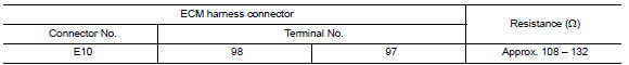
2.CHECK HARNESS FOR OPEN CIRCUIT
- Disconnect the connector of ECM.
- Check the resistance between the ECM harness connector terminals.
3.CHECK POWER SUPPLY AND GROUND CIRCUIT
Check the power supply and the ground circuit of the ECM. Refer to EC-157, "Diagnosis Procedure".
 Main line between A-bag and ABS circuit
Diagnosis Procedure
1.CHECK CONNECTOR
Turn the ignition switch OFF.
Disconnect the battery cable from the negative terminal.
Check the following terminals and connectors for damage, bend and ...
 BCM branch line circuit
Diagnosis Procedure
1.CHECK CONNECTOR
Turn the ignition switch OFF.
Disconnect the battery cable from the negative terminal.
Check the terminals and connectors of the BCM for damage, bend and ...
Other materials:
Main line between dlc and hvac circuit
Diagnosis Procedure
1.CHECK HARNESS CONTINUITY (OPEN CIRCUIT)
Turn the ignition switch OFF.
Disconnect the battery cable from the negative
terminal.
Disconnect the following harness connectors.
ECM
A/C auto amp.
Check the continuity betw ...
Precaution
Precaution for Supplemental Restraint System (SRS) "AIR BAG" and "SEAT
BELT
PRE-TENSIONER"
The Supplemental Restraint System such as "AIR BAG" and "SEAT BELT PRE-TENSIONER",
used along
with a front seat belt, helps to reduce the risk or severity of injury to the
driver a ...
System maintenance
The sensor for the ICC system A is located on
the front of the vehicle.
To keep the ICC system operating properly, be
sure to observe the following:
Always keep the sensor area clean.
Do not strike or damage the areas around
the sensor. Do not touch or remove the
screw located on ...
Nissan Maxima Owners Manual
- Illustrated table of contents
- Safety-Seats, seat belts and supplemental restraint system
- Instruments and controls
- Pre-driving checks and adjustments
- Monitor, climate, audio, phone and voice recognition systems
- Starting and driving
- In case of emergency
- Appearance and care
- Do-it-yourself
- Maintenance and schedules
- Technical and consumer information
Nissan Maxima Service and Repair Manual

0.0059