Nissan Maxima Service and Repair Manual: Control valve
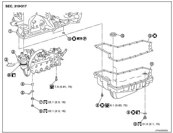
Exploded View
-
Transaxle assembly
-
Control valve
-
Snap ring
-
Collar
-
Manual plate
-
Lock nut
-
Lock nut
-
Oil pan bolt
-
O-ring
-
Drain plug
-
Oil pan
-
Oil pan gasket
-
Magnet
-
Lip seal
A. O-ring
 : NISSAN CVT Fluid NS-2
Removal and Installation
REMOVAL
-
Disconnect battery negative terminal. Refer to PG-67, "Removal and Installation (Battery)".
-
Remove the front fender protector side cover, Refer to EXT-24, "Removal and Installation".
-
Disconnect the CVT unit harness connector. Refer to TM-150, "Removal and Installation Procedure for CVT Unit Connector".
-
Remove the oil pan. Refer to TM-177, "Removal and Installation".
-
Remove oil strainer.
-
Remove the lock nut (1) and (2), and then remove manual plate (3).
 : Front
7. Remove the collar (4) from the manual shaft (A).
CAUTION: Do not drop the collar.
8. Disconnect the primary pressure sensor harness connector (B).
9. Remove the snap ring (1) from the CVT unit harness connector (A).
10. Press the CVT unit harness connector (A) into the transaxle case.
CAUTION: Do not damage the CVT unit harness connector.
NOTE: Clean around the CVT unit harness connector to prevent foreign materials from entering into the transaxle case.
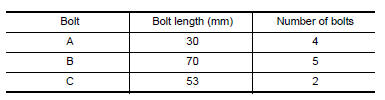
11. Remove the control valve bolts (A), (B) and (C), and then remove the control valve from the transaxle case.
 : Front
CAUTION:
-
Do not drop the control valve, ratio control valve and manual shaft.
-
Confirm position of the shift link for ease of installation.
12. Remove the lip seal (1) from the transaxle case.
CAUTION: Do not reuse lip seal.
 : Front
INSTALLATION
1. Install the lip seal (1) to the transaxle case.
CAUTION: Do not reuse lip seal.
 : Front
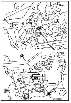
2. Check the harness connector (B), O-ring (C), and the orientation of shift link (A) on the control valve.
CAUTION:
-
Do not touch or wipe out the control valve mating surface.
-
Be careful not to drop the ratio control valve (D), because the return spring in ratio control valve may push out the ratio control valve.
-
Be sure shift link (A) is in the proper position prior to installation.
-
Do not reuse O-ring.
-
Be sure to apply CVT fluid to O-ring (C).
-
Check that a notch (E) of shift link engages with the step motor and that a bracket of shift link engages with a hole (F) of step motor.
-
Place the harness connector on the secondary pressure sensor (G).
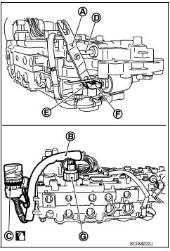
3. Temporarily tighten the control valve with 2 control valve bolts, while adjusting the shift link (A) to engage the notch (C) of shift link with the pin (B) of pulley sensor.
CAUTION:
-
Do not pinch the harness into between the control valve and the transaxle case.
-
Do not damage the control valve while installing.
-
Check that the notch (C) at one end of shift link (A) engages with the pin (B) of pulley sensor. Check that the notch (D) at the other end of shift link (A) engages with step motor and that the bracket of shift link (A) engages with the hole (E) of step motor.
4. Install the control valve bolts (A), (B), and (C).
 : Front
5. Install the collar (1) to the manual shaft (A).
 : Front
6. Install the manual plate (1) while aligning with the groove (A) of the manual valve.
 : Front
7. Install the lock-nut (2), and then the lock-nut (3).
8. Install the CVT unit harness connector (A) to the transaxle case.
 : Front
CAUTION: Engage the notch (B) of CVT unit harness connector with the protrusion (C) of transaxle case.
9. Install the primary pressure sensor harness connector (D)
10. Install the snap ring (1) to the CVT unit harness connector (A).
11. Install the magnet while aligning it with the convex side of oil pan.
CAUTION: Completely eliminate the iron powder from the magnet area of oil pan and the magnet.
12. Install the oil pan. Refer to TM-177, "Removal and Installation".
13. Connect the CVT unit harness connector. Refer to TM-150, "Removal and Installation Procedure for CVT Unit Connector".
14. Fill CVT fluid from CVT fluid charging pipe to the specified level.
CAUTION:
-
Use only Genuine NISSAN CVT Fluid NS-2. Do not mix with other fluid.
-
Using CVT fluid other than Genuine NISSAN CVT Fluid NS-2 will deteriorate in driveability and CVT durability, and may damage the CVT, which is not covered by the warranty.
-
When filling CVT fluid, take care not to spill on heat generating parts such as exhaust.
-
Sufficiently shake the container of CVT fluid before using.
-
Delete CVT fluid deterioration date with CONSULT after changing CVT fluid. Refer to TM-38, "CONSULT Function".
15. Install the front fender side protector. Refer to EXT-24, "Removal and Installation".
16. Connect battery negative terminal. Refer to PG-67, "Removal and Installation (Battery)".
17. Perform the following procedures. Refer to TM-183, "Inspection and Adjustment".
-
Adjustment after installation.
-
Inspection after installation.
Inspection and Adjustment
INSPECTION AFTER REMOVAL
Check oil pan for foreign material.
-
If a large amount of worn material is found, clutch plate may be worn.
-
If iron powder is found, bearings, gears, or clutch plates may be worn.
-
If aluminum powder is found, bushing may be worn, or chips or burrs of aluminum casting parts may enter.
Check points where wear is found in all cases.
ADJUSTMENT AFTER INSTALLATION
Erase the CVT fluid deterioration data. Refer to TM-38, "CONSULT Function".
INSPECTION AFTER INSTALLATION
Check the CVT fluid level, condition and leakage. Refer to TM-155, "Inspection".
 Oil pan
Exploded View
Transaxle assembly
Oil pan bolt
Drain plug
O-ring
Oil pan
Oil pan gasket
Magnet
...
 Secondary speed sensor
Exploded View
Secondary speed sensor
Shim
Transaxle assembly
O-ring
Apply CVT Fluid NS-2
Removal and Installation
REMOVAL
&nb ...
Other materials:
B2618 BCM
Description
BCM controls the various electrical components and simultaneously supplies
power according to the power
supply position.
BCM checks the power supply position internally.
DTC Logic
DTC DETECTION LOGIC
NOTE:
If DTC B2618 is displayed with DTC U1000, first perform the
trou ...
Front power seat adjustment
Operating tips
The power seat motor has an auto-reset
overload protection circuit. If the motor
stops during operation, wait 30 seconds
then reactivate the switch.
Do not operate the power seat switch for a
long period of time when the engine is off.
This will discharge the bat ...
RearView Monitor system limitations
WARNING
Listed below are the system limitations for
RearView Monitor. Failure to operate the
vehicle in accordance with these system
limitations could result in serious injury or
death.
The system cannot completely eliminate
blind spots and may not show every
object.
Underneath the bu ...
Nissan Maxima Owners Manual
- Illustrated table of contents
- Safety-Seats, seat belts and supplemental restraint system
- Instruments and controls
- Pre-driving checks and adjustments
- Monitor, climate, audio, phone and voice recognition systems
- Starting and driving
- In case of emergency
- Appearance and care
- Do-it-yourself
- Maintenance and schedules
- Technical and consumer information
Nissan Maxima Service and Repair Manual

0.0055