Nissan Maxima Service and Repair Manual: Oil pan
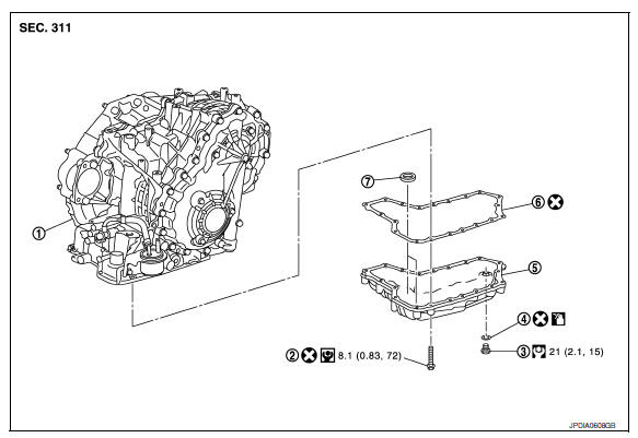
Exploded View
-
Transaxle assembly
-
Oil pan bolt
-
Drain plug
-
O-ring
-
Oil pan
-
Oil pan gasket
-
Magnet
 Apply CVT Fluid NS-2
Removal and Installation
REMOVAL
-
Drain CVT fluid from CVT. Refer to TM-156, "Changing".
-
Remove O-ring from drain plug.
-
Remove oil pan bolts (
 ).
).-
 : Front
-
-
Remove oil pan.
5. Remove oil pan gasket (1) from oil pan (2).
6. Remove magnet (3) from oil pan.
INSTALLATION Installation is in the reverse order of removal.
CAUTION:
-
Completely remove all moisture, oil and old gasket, etc. from the oil pan gasket mating surface of transaxle case and oil pan.
-
Do not reuse oil pan gasket, O-ring and oil pan bolts.
-
Apply CVT fluid to O-ring.
-
Install the oil pan assembly to the transaxle case with the following procedure.
-
Install the oil pan assembly to the transaxle case, and then temporarily tighten the oil pan bolts.
-
CAUTION:
Do not reuse oil pan bolts.
-
Tighten the oil pan bolts in a criss cross pattern to the specified torque.
-
Tighten the oil pan bolts again clockwise to the specified torque.
Inspection
Check foreign materials in oil pan to help determine causes of malfunction. If the CVT fluid is very dark, smells burned, or contains foreign particles, frictional material (clutches) may need replacement. A tacky film that will not wipe clean indicates varnish build up. Varnish can cause valves and clutches to stick and can inhibit pump pressure.
INSPECTION AFTER INSTALLATION
Check for CVT fluid leakage and check CVT fluid level. Refer to TM-155, "Inspection".
 Paddle shifter
Exploded View
Steering column assembly
Paddle shifter (shift-down)
Paddle shifter (shift-up)
Removal and Installation
REMOVAL
Park the ...
 Control valve
Exploded View
Transaxle assembly
Control valve
Snap ring
Collar
Manual plate
Lock nut
Lock nut
...
Other materials:
Center speaker
Description
The AV control unit sends audio signals to the BOSE speaker amp. The BOSE
speaker amp. amplifies the
audio signals before sending them to the center speaker using the audio signal
circuits.
Diagnosis Procedure
1.CONNECTOR CHECK
Check the AV control unit, BOSE speaker amp. and s ...
Front bumper
Exploded View
Tow cover
Engine under cover
Core support cover
Fog lamp cover
Fog lamp (if equipped)
Front bumper fascia
Center support bracket
Upper fascia support
Front bumper upper bracket
Front bumper side bracket
Front bumper fascia seal
Front bumper stiffener ...
Aux in jack
Removal and Installation
REMOVAL
Remove the center console. Refer to IP-14, "Removal and
Installation".
Remove the center console bin box.
Remove the auxiliary input jacks screws (A), then remove the
auxiliary input jacks (1).
INSTALLATION
Installation is in the reverse order of ...
Nissan Maxima Owners Manual
- Illustrated table of contents
- Safety-Seats, seat belts and supplemental restraint system
- Instruments and controls
- Pre-driving checks and adjustments
- Monitor, climate, audio, phone and voice recognition systems
- Starting and driving
- In case of emergency
- Appearance and care
- Do-it-yourself
- Maintenance and schedules
- Technical and consumer information
Nissan Maxima Service and Repair Manual

0.006