Nissan Maxima Service and Repair Manual: ABS
System Diagram
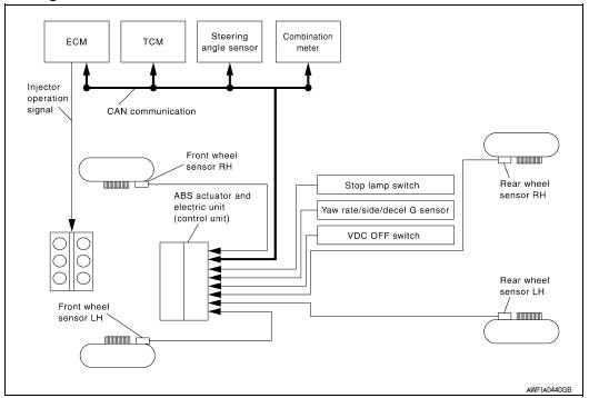
System Description
- Anti-Lock Braking System is a function that detects wheel revolution while braking, electronically controls braking force, and prevents wheel locking during sudden braking. It improves handling stability and maneuverability for avoiding obstacles.
- Electrical system diagnosis by CONSULT is available.
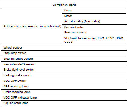
Component Parts Location
- Front wheel sensor LH E19 Front wheel sensor RH E41
- Brake fluid level switch E24
- Parking brake switch E35
- Stop lamp switch E38
- VDC OFF switch M72
- Combination meter M24
- Rear wheel sensor LH C1 Rear wheel sensor RH C2
- Yaw rate/side/decel G sensor M55
- Steering angle sensor M53 (view with steering wheel removed)
- ABS actuator and electric unit (control unit) E26
Component Description
 TCS
TCS
System Diagram
System Description
Traction Control System is a function that electronically controls
engine torque and brake fluid pressure to
ensure the optimum slippage ratio at drive ...
 EBD
EBD
System Diagram
System Description
Electric Brake force Distribution functions as follows:
ABS actuator and electric unit (control unit) detects subtle
slippages between the front and rear ...
Other materials:
Precautions on cruise control
1. CANCEL switch
2. RES+ switch
3. SET- switch
4. ON/OFF cruise switch
If the cruise control system malfunctions, it
cancels automatically.
WARNING
Do not use the cruise control when driving
under the following conditions:
When it is not possible to keep the
vehicle at ...
The parking brake release warning continues sounding, or does not sound
Description
The parking brake warning buzzer sounds continuously during
vehicle travel though the parking brake is
released
The parking brake warning buzzer does not sound at all even though
driving the vehicle with the parking
brake applied.
Diagnosis Procedure
1. CHECK PARKIN ...
Tire dressings
NISSAN does not recommend the use of tire
dressings. Tire manufacturers apply a coating to
the tires to help reduce discoloration of the rubber.
If a tire dressing is applied to the tires, it may
react with the coating and form a compound. This
compound may come off the tire while driving and ...
Nissan Maxima Owners Manual
- Illustrated table of contents
- Safety-Seats, seat belts and supplemental restraint system
- Instruments and controls
- Pre-driving checks and adjustments
- Monitor, climate, audio, phone and voice recognition systems
- Starting and driving
- In case of emergency
- Appearance and care
- Do-it-yourself
- Maintenance and schedules
- Technical and consumer information
Nissan Maxima Service and Repair Manual

0.0056