Nissan Maxima Service and Repair Manual: TCS
System Diagram
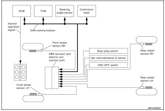
System Description
- Traction Control System is a function that electronically controls
engine torque and brake fluid pressure to
ensure the optimum slippage ratio at drive wheels by computing wheel speed
signals from 4 wheel sensors.
When ABS actuator and electric unit (control unit) detects a spin at drive wheels, it compares wheel speed signals from all 4 wheels. At this time, LH and RH front brake fluid pressure are controlled, while fuel being cut to engine and throttle valve being closed to reduce engine torque by the control unit. Further more, throttle position is continuously controlled to ensure the optimum engine torque at all times.
- During TCS operation, it informs driver of system operation by flashing slip indicator lamp.
- Electrical system diagnosis by CONSULT is available.
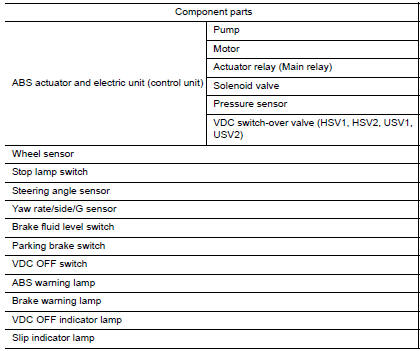
Component Parts Location
- Front wheel sensor LH E19 Front wheel sensor RH E41
- Brake fluid level switch E24
- Parking brake switch E35
- Stop lamp switch E38
- VDC OFF switch M72
- Combination meter M24
- Rear wheel sensor LH C1 Rear wheel sensor RH C2
- Yaw rate/side/decel G sensor M55
- Steering angle sensor M53 (view with steering wheel removed)
- ABS actuator and electric unit (control unit) E26
Component Description
 VDC
VDC
System Diagram
Hydraulic Circuit Diagram
Primary side
VDC/TCS/ABS actuator
Primary side VDC switch-over valve
1 (USV1)
Primary side VDC switch-over valve
1 (HSV1)
Primary ...
 ABS
ABS
System Diagram
System Description
Anti-Lock Braking System is a function that detects wheel revolution
while braking, electronically controls
braking force, and prevents wheel locking d ...
Other materials:
Engine block heater (if so equipped)
Engine block heaters are used to assist with cold
temperature starting.
The engine block heater should be used when
the outside temperature is 20F (-7C) or lower.
WARNING
Do not use your engine block heater
with an ungrounded electrical system or
a 2-pronged adapter. You can be serious ...
P0725 engine speed
Description
The engine speed signal is transmitted from ECM to TCM via CAN communication
line.
DTC Logic
DTC DETECTION LOGIC
DTC CONFIRMATION PROCEDURE
CAUTION:
Always drive vehicle at a safe speed.
NOTE:
Immediately after performing any "DTC CONFIRMATION PROCEDURE", always turn
igni ...
Condenser
CONDENSER
CONDENSER : Removal and Installation
REMOVAL
Discharge the refrigerant. Refer to HA-28, "Recycle Refrigerant".
Remove the RH hoodledge cover.
Remove the front bumper fascia. Refer to EXT-16, "Removal and
Installation".
Disconnect the high-pressure pipe from the condenser pip ...
Nissan Maxima Owners Manual
- Illustrated table of contents
- Safety-Seats, seat belts and supplemental restraint system
- Instruments and controls
- Pre-driving checks and adjustments
- Monitor, climate, audio, phone and voice recognition systems
- Starting and driving
- In case of emergency
- Appearance and care
- Do-it-yourself
- Maintenance and schedules
- Technical and consumer information
Nissan Maxima Service and Repair Manual

0.0061