
Nissan Maxima Owners Manual: Exterior rear
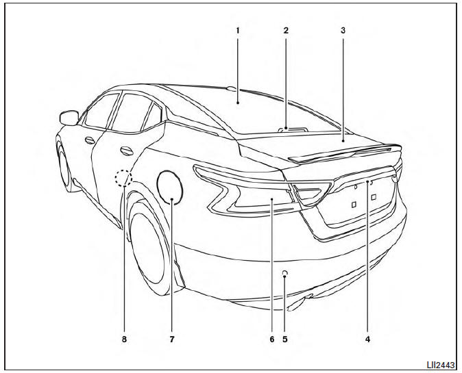
- Rear window defroster switch
- High-mounted stop light
- Interior trunk lid release. Trunk lid
- Exterior trunk lid release/request button. Rearview camera
- Rear sonar sensors (if so equipped)
- Replacing bulbs
- Fuel-filler door. Fuel recommendation
- Child safety rear door locks
Refer to the page number indicated in parentheses for operating details.
 Exterior front
Engine hood
Wiper and washer switch
Windshield
Power windows
Door locks NISSAN Intelligent Key. Keys
Mirrors. Side view camera (if so equipped)
Tire pressure. Flat tire. Tire chains ...
 Passenger compartment
Interior trunk access
Power moonroof (if so equipped)
Sun visors
Map lights
Rearview mirror. HomeLink Universal Transceiver
Glove box
Cup holders
Console box
Refer to the page ...
Other materials:
Hazard switch
Exploded View
Hazard switch
Cluster lid D
Removal and Installation
REMOVAL
Remove cluster lid D. Refer to IP-18, "Removal and Installation".
Disconnect the harness connector from the hazard switch.
Remove the hazard switch.
INSTALLATION
Installation is in the reverse order o ...
Power supply and ground circuit
BCM
BCM : Diagnosis Procedure
1. CHECK FUSE AND FUSIBLE LINK
Check if the following BCM fuses or fusible link are blown.
2. CHECK POWER SUPPLY CIRCUIT
Turn ignition switch OFF.
Disconnect BCM.
Check voltage between BCM harness connector and ground.
3. CHECK GROUND CIRCUIT
Che ...
Electric ignition system
System Diagram
System Description
INPUT/OUTPUT SIGNAL CHART
*1: This signal is sent to the ECM via the CAN communication line.
*2: ECM determines the start signal status by the signals of engine speed and
battery voltage.
SYSTEM DESCRIPTION
Ignition order: 1 - 2 - 3 - 4 - 5 - 6
The ...
Nissan Maxima Owners Manual
- Illustrated table of contents
- Safety-Seats, seat belts and supplemental restraint system
- Instruments and controls
- Pre-driving checks and adjustments
- Monitor, climate, audio, phone and voice recognition systems
- Starting and driving
- In case of emergency
- Appearance and care
- Do-it-yourself
- Maintenance and schedules
- Technical and consumer information
Nissan Maxima Service and Repair Manual

0.0092