Nissan Maxima Owners Manual: Passenger compartment
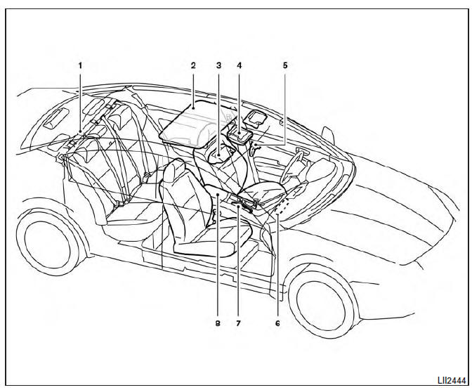
- Interior trunk access
- Power moonroof (if so equipped)
- Sun visors
- Map lights
- Rearview mirror. HomeLink Universal Transceiver
- Glove box
- Cup holders
- Console box
Refer to the page number indicated in parentheses for operating details.
 Exterior rear
Rear window defroster switch
High-mounted stop light
Interior trunk lid release. Trunk lid
Exterior trunk lid release/request button. Rearview camera
Rear sonar sensors (if so equipped) ...
 Instrument Panel
Vent
Headlight/fog light/turn signal switch
Supplemental front-impact air bag. Horn
Meters and gauges. Warning and indicator lights. Vehicle information
display
Paddle shifters (if s ...
Other materials:
Precaution
Precaution for Supplemental Restraint System (SRS) "AIR BAG" and
"SEAT BELT PRE-TENSIONER"
The Supplemental Restraint System such as "AIR BAG" and "SEAT BELT
PRE-TENSIONER", used along with a front seat belt, helps to reduce the risk
or severity of injury to the driver and front passenger for ...
System maintenance
The two radar sensors 1 for the BSW and
RCTA systems are located near the rear bumper.
Always keep the area near the radar sensors
clean.
The radar sensors may be blocked by temporary
ambient conditions such as splashing water, mist
or fog.
The blocked condition may also be caused b ...
Front washer
WASHER TUBE
WASHER TUBE : Layout
Washer nozzle (LH)
Washer nozzle hose (LH)
Washer nozzle (RH)
Washer nozzle hose (RH)
Y-tube connector
Washer tank hose
Washer tank
Tube connectors
Clip
FRONT WASHER NOZZLE
FRONT WASHER NOZZLE : Removal and Installation
REMOVAL
...
Nissan Maxima Owners Manual
- Illustrated table of contents
- Safety-Seats, seat belts and supplemental restraint system
- Instruments and controls
- Pre-driving checks and adjustments
- Monitor, climate, audio, phone and voice recognition systems
- Starting and driving
- In case of emergency
- Appearance and care
- Do-it-yourself
- Maintenance and schedules
- Technical and consumer information
Nissan Maxima Service and Repair Manual

0.0052