Nissan Maxima Owners Manual: Instrument Panel
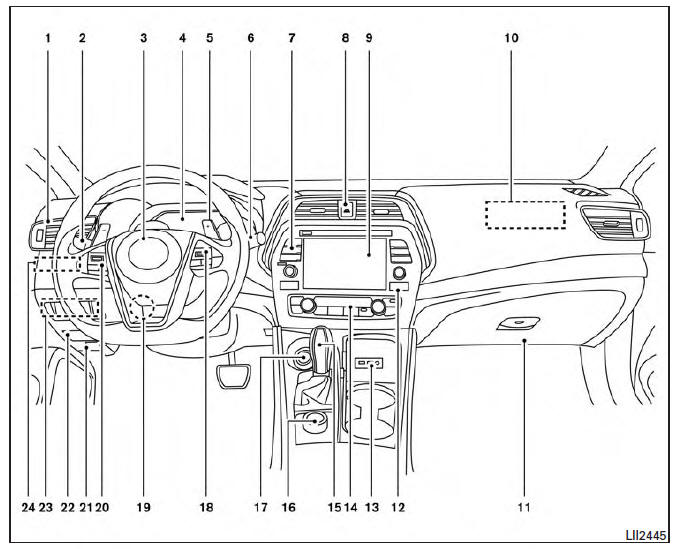
- Vent
- Headlight/fog light/turn signal switch
- Supplemental front-impact air bag. Horn
- Meters and gauges. Warning and indicator lights. Vehicle information display
- Paddle shifters (if so equipped)
- Wiper and washer switch
- Audio controls*. Navigation controls*
- Hazard warning flasher switch
- Navigation display*. Audio display*
- Front passenger supplemental air bag.
- Glove box
- Front passenger air bag status light
- AUX input/USB port*
- Heater and air conditioning controls
- Shift lever
- Display Commander*
- Push-button ignition switch
- Bluetooth Hands-Free Phone System. Cruise control switches (if so equipped). Intelligent Cruise Control . Intelligent Cruise Control
- Tilt and telescopic steering
- Audio control switches*. Vehicle information display control switches
- Hood release
- Fuse box
- Heated steering wheel switch (if so equipped). Vehicle Dynamic Control (VDC) OFF switch. Trunk release switch. Rear power sunshade switch (if so equipped)
- Instrument brightness control. Twin trip odometer reset switch
*: Refer to the separate Navigation System Owner's Manual.
Refer to the page number indicated in parentheses for operating details.
 Passenger compartment
Interior trunk access
Power moonroof (if so equipped)
Sun visors
Map lights
Rearview mirror. HomeLink Universal Transceiver
Glove box
Cup holders
Console box
Refer to the page ...
 Engine compartment check locations
VQ35DE engine
Engine coolant reservoir
Drive belt location
Engine oil filler cap
Brake fluid reservoir
Air cleaner
Fuse block
Fuse block/Fusible links
Fusible links
Battery
E ...
Other materials:
B2623 inside key antenna 3
Description
Detects whether Intelligent Key is inside the vehicle.
Installed in the trunk room.
DTC Logic
NOTE:
The Signal Tech II Tool (J-50190) can be used to perform the following
functions. Refer to the Signal Tech II
User Guide for additional information.
Check Intelligent Ke ...
Paddle shifter
Exploded View
Steering column assembly
Paddle shifter (shift-down)
Paddle shifter (shift-up)
Removal and Installation
REMOVAL
Park the vehicle on a level surface.
Remove the driver air bag module. Refer to
SR-12, "Expl ...
Precautions
Precaution for Supplemental Restraint System (SRS) "AIR BAG" and "SEAT
BELT
PRE-TENSIONER"
The Supplemental Restraint System such as "AIR BAG" and "SEAT BELT
PRE-TENSIONER", used along
with a front seat belt, helps to reduce the risk or severity of injury to the
driver ...
Nissan Maxima Owners Manual
- Illustrated table of contents
- Safety-Seats, seat belts and supplemental restraint system
- Instruments and controls
- Pre-driving checks and adjustments
- Monitor, climate, audio, phone and voice recognition systems
- Starting and driving
- In case of emergency
- Appearance and care
- Do-it-yourself
- Maintenance and schedules
- Technical and consumer information
Nissan Maxima Service and Repair Manual

0.0055