Nissan Maxima Service and Repair Manual: B1134 - B1137 side airbag module LH
Description
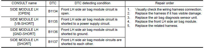
DTC B1134 - B1137 FRONT LH SIDE AIR BAG MODULE
The front LH side air bag module is wired to the air bag diagnosis sensor
unit. The air bag diagnosis sensor
unit will monitor for opens and shorts in
detected lines to the front LH side air bag module.
PART LOCATION
DTC Logic
DTC DETECTION LOGIC
With CONSULT
DTC CONFIRMATION PROCEDURE (With CONSULT)
1.CHECK SELF-DIAG RESULT
- Turn ignition switch ON.
- Check for DTC using CONSULT
2.ERASE SELF-DIAG RESULT
Erase the DTC using CONSULT.
DTC CONFIRMATION PROCEDURE (Without CONSULT)
1.CHECK SELF-DIAG RESULT
- Turn ignition switch ON.
- Check the air bag warning lamp status. Refer to SRC-14, "Trouble Diagnosis without CONSULT".
NOTE:
SRS will not enter diagnosis mode if
no malfunction is detected in user mode.
Diagnosis Procedure
1.HARNESS CONNECTOR
Visually inspect all applicable harness connectors for the following:
- Visible damage to connector or terminal
- Loose terminal
- Poor connection
NOTE:
All harness connectors should be
inspected from the air bag diagnosis sensor unit to the end component
(including any in-line connectors).
2.CONFIRM DTC
- Reconnect all harness connectors.
- Turn ignition switch ON.
- Check for DTC using CONSULT.
3.WIRING HARNESS
Check the wiring harness for visible damage.
NOTE:
The entire wiring harness should be
inspected from the air bag diagnosis sensor unit to the end component
(including any in-line connectors).
4.CONFIRM DTC
- Reconnect all harness connectors.
- Turn ignition switch ON.
- Check for DTC using CONSULT.
5.AIR BAG DIAGNOSIS SENSOR UNIT
- Replace the air bag diagnosis sensor unit. Refer to SR-31, "Removal and Installation".
- Turn ignition switch ON.
- Check for DTC using CONSULT.
6.SIDE AIR BAG MODULE LH
- Replace the side air bag module LH. Refer to SR-21, "Removal and Installation".
- Turn ignition switch ON.
- Check for DTC using CONSULT.
7.RELATED HARNESS
Replace the related harness.
 B1065 - B1068, B1070 - B1073 passenger airbag module
Description
DTC B1065 - B1068, B1070 - B1073 PASSENGER AIR BAG MODULE
The passenger air bag module is dual stage and wired to the air bag diagnosis
sensor unit. The air bag diagnosissensor unit wi ...
 B1129 - B1132 side airbag module RH
Description
DTC B1129 - B1132 FRONT RH SIDE AIR BAG MODULE
The front RH side air bag module is wired to the air bag diagnosis sensor
unit. The air bag diagnosis sensorunit will monitor for opens a ...
Other materials:
Intelligent key system/engine start function symptoms
Symptom Table
Engine cannot be started with all Intelligent Keys.
CAUTION:
Follow Trouble Diagnosis Flowchart
referring to "SEC-4, "Work Flow"". Determine malfunctioning
condition before performing this diagnosis.
Check that vehicle is under the
condition shown in "Conditio ...
Brakes
If the brakes do not operate properly, have the
brakes checked. it is recommended that you visit
a NISSAN dealer for this service.
Self-adjusting brakes
Your vehicle is equipped with self-adjusting
brakes.
The front and rear disc-type brakes self-adjust
every time the brake pedal is applied ...
Diagnosis system (AV control unit)
Description
The AV control unit diagnosis function starts up with multifunction
switch operation and the AV control unit
performs a diagnosis for each unit in the system during the on board
diagnosis.
Perform a CONSULT diagnosis if the on board diagnosis does not start,
e.g., the s ...
Nissan Maxima Owners Manual
- Illustrated table of contents
- Safety-Seats, seat belts and supplemental restraint system
- Instruments and controls
- Pre-driving checks and adjustments
- Monitor, climate, audio, phone and voice recognition systems
- Starting and driving
- In case of emergency
- Appearance and care
- Do-it-yourself
- Maintenance and schedules
- Technical and consumer information
Nissan Maxima Service and Repair Manual

0.0069