Nissan Maxima Owners Manual: Rear-facing child restraint installation using LATCH
For additional information, refer to all Warnings and Cautions in the "Child safety" and "Child restraints" sections of this manual before installing a child restraint.
Do not use the lower anchors if the combined weight of the child and the child restraint exceeds 65 lbs (29.5 kg). If the combined weight of the child and the child restraint is greater than 65 lbs (29.5 kg), use the vehicle's seat belt (not the lower anchors) to install the child restraint. Be sure to follow the child restraint manufacturer's instructions for installation.
Follow these steps to install a rear-facing child restraint using the LATCH system: 1. Position the child restraint on the seat. Always follow the child restraint manufacturer's instructions.
Rear-facing webbing-mounted - step 2
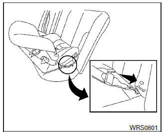
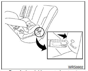
2. Secure the child restraint anchor attachments to the LATCH lower anchors. Check to make sure the LATCH attachment is properly attached to the lower anchors.
Rear-facing rigid-mounted - step 2
Rear-facing - step 3
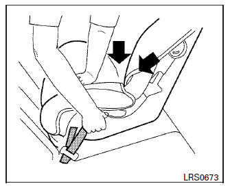
3. For child restraints that are equipped with webbing-mounted attachments, remove any additional slack from the anchor attachments.
Press downward and rearward firmly in the center of the child restraint with your hand to compress the vehicle seat cushion and seatback while tightening the webbing of the anchor attachments.
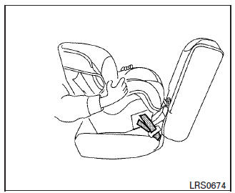
Rear-facing - step 4
4. After attaching the child restraint, test it before you place the child in it. Push it from side to side while holding the child restraint near the LATCH attachment path. The child restraint should not move more than 1 inch (25 mm), from side to side. Try to tug it forward and check to see if the LATCH attachment holds the restraint in place. If the restraint is not secure, tighten the LATCH attachment as necessary, or put the restraint in another seat and test it again. You may need to try a different child restraint or try installing by using the vehicle seat belt (if applicable). Not all child restraints fit in all types of vehicles.
5. Check to make sure the child restraint is properly secured prior to each use. If the child restraint is loose, repeat steps 1 through 4.
 LATCH (Lower Anchors and Tethers for CHildren) system
LATCH system lower anchor locations
Your vehicle is equipped with special anchor
points that are used with LATCH system compatible
child restraints. This system may also be
referred to as the ...
 Rear-facing child restraint installation using the seat belts
WARNING
The three-point seat belt with Automatic
Locking Retractor (ALR) must be used when
installing a child restraint. Failure to use the
ALR mode will result in the child restraint
not being p ...
Other materials:
Climate controlled seat
Wiring Diagram
...
TPMS
System Diagram
System Description
DESCRIPTION
During driving, the tire pressure monitoring system receives the signal
transmitted from the transmitter installed in each wheel, and turns on the
low tire pressure warning lamp when the tire pressure becomes low.
The
control unit (BCM) for t ...
Warning function
System Description
OPERATION DESCRIPTION
The warning functions are as follows and are given to the user as warning
information and warnings using
combinations of Intelligent Key warning buzzer, KEY warning lamp, key slot
illumination and combination
meter display in combination meter.
...
Nissan Maxima Owners Manual
- Illustrated table of contents
- Safety-Seats, seat belts and supplemental restraint system
- Instruments and controls
- Pre-driving checks and adjustments
- Monitor, climate, audio, phone and voice recognition systems
- Starting and driving
- In case of emergency
- Appearance and care
- Do-it-yourself
- Maintenance and schedules
- Technical and consumer information
Nissan Maxima Service and Repair Manual

0.0062