Nissan Maxima Service and Repair Manual: Diagnosis system (IPDM E/R)
Diagnosis Description
AUTO ACTIVE TEST
Description
In auto active test mode, the IPDM E/R sends a drive signal to the following systems to check their operation.
- Oil pressure warning lamp
- Front wiper (LO, HI)
- Parking lamps
- Side marker lamps
- License plate lamps
- Tail lamps
- Front fog lamps (if equipped)
- Headlamps (LO, HI)
- A/C compressor (magnet clutch)
- Cooling fans
Operation Procedure
- Close the hood and lift the wiper arms from the windshield. (Prevent
windshield damage due to wiper
operation)
NOTE:
When auto active test is performed with hood opened, sprinkle water on windshield beforehand. - Turn ignition switch OFF.
- Turn the ignition switch ON, and within 20 seconds, press the
front door switch LH 10 times. Then turn the
ignition switch OFF.
CAUTION:
Close front door RH. - Turn the ignition switch ON within 10 seconds. After that the horn
sounds once and the auto active test
starts. - The oil pressure warning lamp starts blinking when the auto active test starts.
- After a series of the following operations is repeated 3 times, auto active test is completed.
NOTE:
When auto active test mode has to be
cancelled halfway through test, turn ignition switch OFF.
CAUTION:
- If auto active test mode cannot be actuated, check door switch
system. Refer to DLK-67,
"Component Function Check". - Do not start the engine.
Inspection in Auto Active Test Mode
When auto active test mode is actuated, the following 6 steps are repeated 3 times.
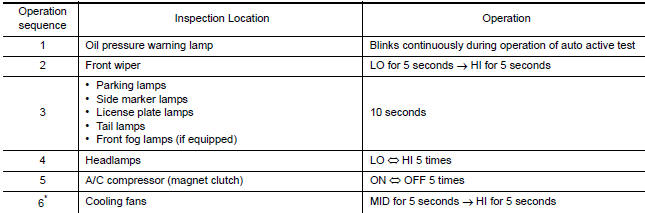
*: Outputs duty ratio of 50% for 5 seconds → duty ratio of 100% for 5 seconds on the cooling fan control module.
Concept of auto active test
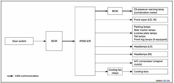
- IPDM E/R starts the auto active test with the door switch signals
transmitted by BCM via CAN communication.
Therefore, the CAN communication line between IPDM E/R and BCM is considered normal if the auto
active test starts successfully. - The auto active test facilitates troubleshooting if any systems controlled by IPDM E/R cannot be operated.
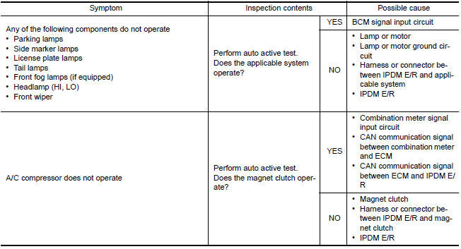
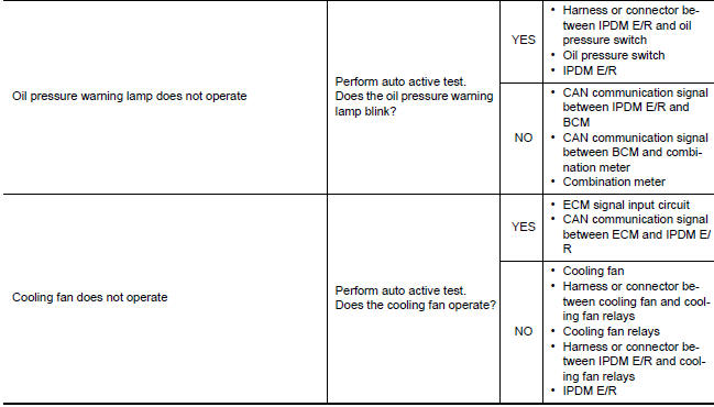
Diagnosis chart in auto active test mode
CONSULT Function (IPDM E/R)
APPLICATION ITEM
CONSULT performs the following functions via CAN communication with IPDM E/R.
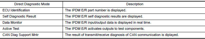
ECU IDENTIFICATION
The IPDM E/R part number is displayed.
SELF DIAGNOSTIC RESULT
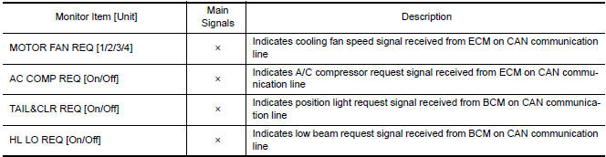
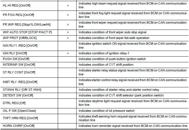
DATA MONITOR
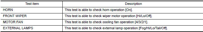
ACTIVE TEST
CAN DIAG SUPPORT MNTR
 Diagnosis system (BCM)
COMMON ITEM
COMMON ITEM : CONSULT Function (BCM - COMMON ITEM)
APPLICATION ITEM
CONSULT performs the following functions via CAN communication with BCM.
SYSTEM APPLICATION
BCM can perform the f ...

Other materials:
Steering switch
Description
When one of the steering wheel audio control switches is pushed, the
resistance in steering switch circuit changes depending on which button is
pushed.
Diagnosis Procedure
1.CHECK STEERING SWITCH RESISTANCE
Disconnect steering switch connector M88.
Check resistance betwe ...
Microphone signal circuit
Description
Voice signals are transmitted from the microphone to the Bluetooth control
unit using the microphone signal circuits.
Diagnosis Procedure
1.CHECK HARNESS BETWEEN BLUETOOTH CONTROL UNIT AND MICROPHONE
Turn ignition switch OFF.
Disconnect Bluetooth control unit connector and ...
Refrigerant pressure sensor
Description
The refrigerant pressure sensor is installed at the condenser of the air
conditioner system. The sensor uses an
electrostatic volume pressure transducer to convert refrigerant pressure to
voltage. The voltage signal is sent
to ECM, and ECM controls cooling fan system.
Compo ...
Nissan Maxima Owners Manual
- Illustrated table of contents
- Safety-Seats, seat belts and supplemental restraint system
- Instruments and controls
- Pre-driving checks and adjustments
- Monitor, climate, audio, phone and voice recognition systems
- Starting and driving
- In case of emergency
- Appearance and care
- Do-it-yourself
- Maintenance and schedules
- Technical and consumer information
Nissan Maxima Service and Repair Manual

0.0068