Nissan Maxima Service and Repair Manual: Combination meter
Removal and Installation
REMOVAL
-
Disconnect the negative battery terminal. Refer to PG-67, "Removal and Installation (Battery)".
-
Remove the cluster lid A. Refer to IP-16, "Removal and Installation".
-
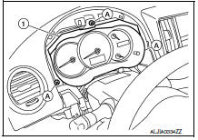
Remove the combination meter screws (A) using power tools.
-
Pull out the combination meter (1).
-
Disconnect the harness connectors from the combination meter (1) and remove.
INSTALLATION
Installation is in the reverse order of removal.

 Meter control switch
Removal and Installation
REMOVAL
Disconnect the negative battery terminal. Refer
to PG-67, "Removal and Installation (Battery)".
Remove the cluster lid A. Refer to IP-16 ...
Other materials:
Heated steering wheel switch (if so equipped)
The heated steering wheel system is designed to
operate only when the surface temperature of the
steering wheel is below 68F (20C).
Push the heated steering wheel switch to warm
the steering wheel after the engine starts. The
indicator light will come on.
If the surface temperature of ...
C1155 BR fluid level low
Description
The brake fluid level switch converts the brake fluid level to an electric
signal and transmits it to the ABS actuator
and electric unit (control unit).
DTC Logic
DTC DETECTION LOGIC
DTC CONFIRMATION PROCEDURE
1.CHECK SELF-DIAGNOSIS RESULTS
Check the self-diagnosis results. ...
Intake Manifold Collector
Removal and Installation
Intake manifold collector
Intake manifold collector gasket
Electric throttle control actuator gasket
Electric throttle control actuator
Refer to INSTALLATION
Refer to INSTALLATION
WARNING: To avoid the danger of being
scalded, do not drain the coolan ...
Nissan Maxima Owners Manual
- Illustrated table of contents
- Safety-Seats, seat belts and supplemental restraint system
- Instruments and controls
- Pre-driving checks and adjustments
- Monitor, climate, audio, phone and voice recognition systems
- Starting and driving
- In case of emergency
- Appearance and care
- Do-it-yourself
- Maintenance and schedules
- Technical and consumer information
Nissan Maxima Service and Repair Manual

0.0058