Nissan Maxima Service and Repair Manual: Meter control switch
Removal and Installation
REMOVAL
-
Disconnect the negative battery terminal. Refer to PG-67, "Removal and Installation (Battery)".
-
Remove the cluster lid A. Refer to IP-16, "Removal and Installation".
-
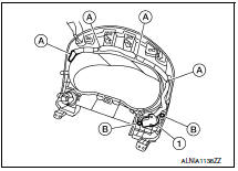
Detach the combination meter control switch harness clips (A).
-
Remove the combination meter control switch screws (B) and remove the combination meter control switch (1).
INSTALLATION
Installation is in the reverse order of removal.
 Combination meter
Removal and Installation
REMOVAL
Disconnect the negative battery terminal. Refer
to PG-67, "Removal and Installation (Battery)".
Remove the cluster lid A. Refer to IP-16 ...
 Unit disassembly and assembly
COMBINATION METER
Disassembly and Assembly
DISASSEMBLY
Remove the combination meter. Refer to MWI-122,
"Removal and Installation".
Remove the combination meter lens (1) ...
Other materials:
Brake pedal
Exploded View
Clevis pin
Snap pin
Stop lamp switch
ASCD cancel switch
Clip
Brake pedal assembly
Brake pedal pad
NOTE:
The clevis pin must be installed from the RH side as shown.
Removal and Installation
REMOVAL
Remove instrument lower panel LH and lower knee protec ...
B2632, B2633 air mix door motor (driver side)
Description
COMPONENT DESCRIPTION
Air Mix Door Motor (driver side)
The air mix door motor (driver side) (1) is attached to the heater
&
cooling unit assembly.
It rotates so that the air mix door is opened or closed to a
position
set by the A/C auto amp.
Motor rotation is then ...
CVT system
System Diagram
Component Parts Location
CVT shift selector assembly (Manual
mode select switch and manual
mode position select switch)
Secondary speed sensor
CVT unit harness connector
TCM
Accelerator pedal position (APP)
sensor
Stop ...
Nissan Maxima Owners Manual
- Illustrated table of contents
- Safety-Seats, seat belts and supplemental restraint system
- Instruments and controls
- Pre-driving checks and adjustments
- Monitor, climate, audio, phone and voice recognition systems
- Starting and driving
- In case of emergency
- Appearance and care
- Do-it-yourself
- Maintenance and schedules
- Technical and consumer information
Nissan Maxima Service and Repair Manual

0.0055