Nissan Maxima Service and Repair Manual: RGB (R: red) signal circuit
Description
Transmit the image displayed with AV control unit with RGB signal to the display unit.
Diagnosis Procedure
1.CHECK CONTINUITY RGB (R: RED) SIGNAL CIRCUIT
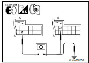
- Turn ignition switch OFF.
- Disconnect display unit connector M141 and AV control unit connector M154.
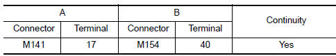
- Check continuity between display unit harness connector M141 (A) terminal 17 and AV control unit harness connector M154 (B) terminal 40
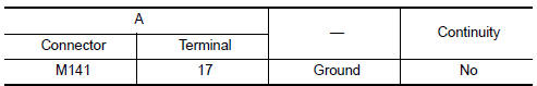
- Check continuity between display unit harness connector M141 (A) terminal 17 and ground.
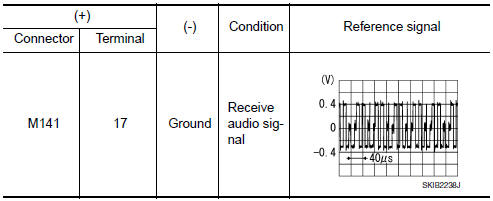
2.CHECK RGB (R: RED) SIGNAL
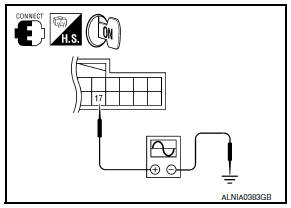
- Connect display unit connector M141 and AV control unit connector M154.
- Turn ignition switch ON.
- Check signal between display unit harness connector M141 terminal 17 and ground.
 Power supply and ground circuit
AV CONTROL UNIT
AV CONTROL UNIT : Diagnosis Procedure
1.CHECK FUSES
Check that the following fuses of the AV control unit are not blown.
2.POWER SUPPLY CIRCUIT CHECK
Disconnect AV cont ...
 RGB (G: green) signal circuit
Description
Transmit the image displayed with AV control unit with RGB signal to the
display unit.
Diagnosis Procedure
1.CHECK CONTINUITY RGB (G: GREEN) SIGNAL CIRCUIT
Turn ignition switc ...
Other materials:
ABS branch line circuit
Diagnosis Procedure
1.CHECK CONNECTOR
Turn the ignition switch OFF.
Disconnect the battery cable from the negative terminal.
Check the terminals and connectors of the ABS actuator and
electric unit (control unit) for damage, bend
and loose connection (unit side and connector side).
...
P0078, P0084 EVT control magnet retarder
Description
Exhaust valve timing control magnet retarder (1) controls the shut/
open timing of the exhaust valve by ON/OFF pulse duty signals sent
from the ECM.
The longer pulse width retards valve timing.
The shorter pulse width advances valve timing.
DTC Logic
DTC DETECTION LOGIC
...
DLC branch line circuit
Diagnosis Procedure
1.CHECK CONNECTOR
Turn the ignition switch OFF.
Disconnect the battery cable from the negative terminal.
Check the terminals and connectors of the data link connector for
damage, bend and loose connection
(connector side and harness side).
2.CHECK HARNESS FOR OP ...
Nissan Maxima Owners Manual
- Illustrated table of contents
- Safety-Seats, seat belts and supplemental restraint system
- Instruments and controls
- Pre-driving checks and adjustments
- Monitor, climate, audio, phone and voice recognition systems
- Starting and driving
- In case of emergency
- Appearance and care
- Do-it-yourself
- Maintenance and schedules
- Technical and consumer information
Nissan Maxima Service and Repair Manual

0.0072