Nissan Maxima Service and Repair Manual: RGB (G: green) signal circuit
Description
Transmit the image displayed with AV control unit with RGB signal to the display unit.
Diagnosis Procedure
1.CHECK CONTINUITY RGB (G: GREEN) SIGNAL CIRCUIT
- Turn ignition switch OFF.
- Disconnect display unit connector M141 and AV control unit connector M154.
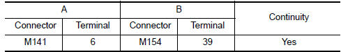
- Check continuity between display unit harness connector M141 (A) terminal 6 and AV control unit harness connector M154 (B) terminal 39.
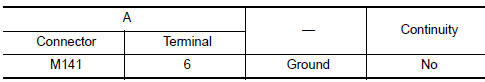
- Check continuity between display unit harness connector M141 (A) terminal 6 and ground
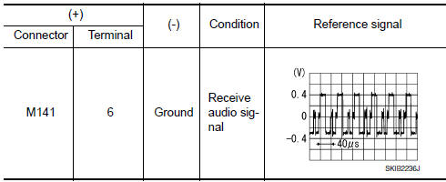
2.CHECK RGB (G: GREEN) SIGNAL
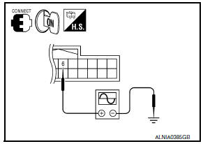
- Connect display unit connector M141 and AV control unit connector M154.
- Turn ignition switch ON.
- Check signal between display unit harness connector M141 terminal 6 and ground.
 RGB (R: red) signal circuit
Description
Transmit the image displayed with AV control unit with RGB signal to the
display unit.
Diagnosis Procedure
1.CHECK CONTINUITY RGB (R: RED) SIGNAL CIRCUIT
Turn ignition switch ...
 RGB (B: blue) signal circuit
Description
Transmit the image displayed with AV control unit with RGB signal to the
display unit.
Diagnosis Procedure
1.CHECK CONTINUITY RGB (B: BLUE) SIGNAL CIRCUIT
Turn ignition switch ...
Other materials:
HVAC branch line circuit
Diagnosis Procedure
1.CHECK CONNECTOR
Turn the ignition switch OFF.
Disconnect the battery cable from the negative terminal.
Check the terminals and connectors of the A/C auto amp. for
damage, bend and loose connection (unit
side and connector side).
2.CHECK HARNESS FOR OPEN CIRCUI ...
U1000 CAN comm circuit
Description
CAN (Controller Area Network) is a serial communication line for real time
application. It is an on-vehicle multiplex
communication line with high data communication speed and excellent error
detection ability. Many electronic
control units are equipped onto a vehicle, and each co ...
Precaution
Precaution for Supplemental Restraint System (SRS) "AIR BAG" and
"SEAT BELT PRE-TENSIONER"
The Supplemental Restraint System such as "AIR BAG" and "SEAT BELT
PRE-TENSIONER", used along with a front seat belt, helps to reduce the risk
or severity of injury to the driver and front passenger for ...
Nissan Maxima Owners Manual
- Illustrated table of contents
- Safety-Seats, seat belts and supplemental restraint system
- Instruments and controls
- Pre-driving checks and adjustments
- Monitor, climate, audio, phone and voice recognition systems
- Starting and driving
- In case of emergency
- Appearance and care
- Do-it-yourself
- Maintenance and schedules
- Technical and consumer information
Nissan Maxima Service and Repair Manual

0.0066