Nissan Maxima Service and Repair Manual: Horizontal synchronizing (HP) signal circuit
Description
In composite image (AUX image, camera image), transmit the vertical synchronizing (VP) signal and horizontal synchronizing (HP) signal from display unit to AV control unit so as to synchronize the RGB images displayed with AV control unit such as the image quality adjusting menu, etc.
Diagnosis Procedure
1.CHECK CONTINUITY HORIZONTAL SYNCHRONIZING (HP) SIGNAL CIRCUIT
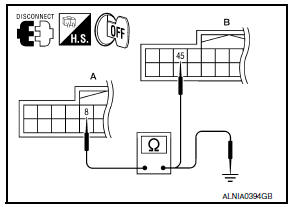
- Turn ignition switch OFF.
- Disconnect display unit connector M141 and AV control unit connector M154.
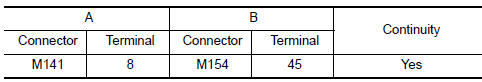
- Check continuity between display unit harness connector M141 (A) terminal 8 and AV control unit harness connector M154 (B) terminal 45.
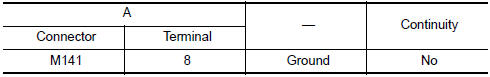
- Check continuity between display unit harness connector M141 (A) terminal 8 and ground.
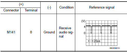
2.CHECK HORIZONTAL SYNCHRONIZING (HP) SIGNAL
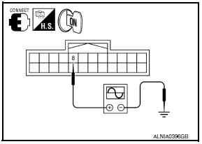
- Connect display unit connector M141 and AV control unit connector M154.
- Turn ignition switch ON.
- Check signal between display unit harness connector M141 terminal 8 and ground.
 RGB area (YS) signal circuit
Description
Transmits the display area of RGB image displayed by AV control unit with RGB
area (YS) signal to display
unit.
Diagnosis Procedure
1.CHECK CONTINUITY RGB AREA (YS) SIGNAL CIRCUIT
...
 Vertical synchronizing (VP) signal circuit
Description
In composite image (AUX image, camera image), transmit the vertical
synchronizing (VP) signal and horizontal
synchronizing (HP) signal from display unit to AV control unit so as to
...
Other materials:
Intake Manifold Collector
Removal and Installation
Intake manifold collector
Intake manifold collector gasket
Electric throttle control actuator gasket
Electric throttle control actuator
Refer to INSTALLATION
Refer to INSTALLATION
WARNING: To avoid the danger of being
scalded, do not drain the coolan ...
Car phone or CB radio
When installing a CB, ham radio or car phone in
your vehicle, be sure to observe the following
precautions; otherwise, the new equipment may
adversely affect the engine control system and
other electronic parts.
WARNING
A cellular phone should not be used for
any purpose while driving so ...
Seat memory switch
Description
Seat memory switch is installed to the front door LH trim. The operation
signal is input to the driver seat control unit when the seat memory switch
is operated.
Component Function Check
1. CHECK FUNCTION
Select ""MEMORY SW 1", "MEMORY SW 2", "SET SW" in "DATA MONITOR"
mode ...
Nissan Maxima Owners Manual
- Illustrated table of contents
- Safety-Seats, seat belts and supplemental restraint system
- Instruments and controls
- Pre-driving checks and adjustments
- Monitor, climate, audio, phone and voice recognition systems
- Starting and driving
- In case of emergency
- Appearance and care
- Do-it-yourself
- Maintenance and schedules
- Technical and consumer information
Nissan Maxima Service and Repair Manual

0.0055