Nissan Maxima Service and Repair Manual: Telescopic sensor
Description
- The telescopic sensor is installed to the steering column assembly.
- The pulse signal is input to the driver seat control unit when telescopic is performed.
- The driver seat control unit counts the pulse and calculates the telescopic amount of the steering column.
Component Function Check
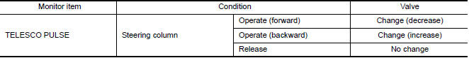
1.CHECK FUNCTION
- Select "TELESCO PULSE" in "DATA MONITOR" mode with CONSULT.
- Check telescopic sensor signal under the following conditions.
Diagnosis Procedure
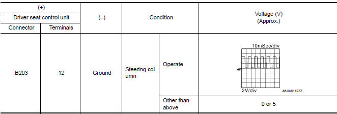
1. CHECK TELESCOPIC SENSOR SIGNAL
- Turn ignition switch ON.
- Check voltage signal between driver seat control unit connector and ground with oscilloscope.
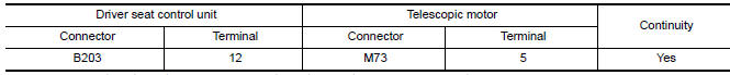
2. CHECK TELESCOPIC SENSOR CIRCUIT
- Turn ignition switch OFF.
- Disconnect driver seat control unit and telescopic motor.
- Check continuity between driver seat control unit harness connector and telescopic motor harness connector.
- Check continuity between driver seat control unit harness connector and ground.

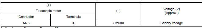
3. CHECK TELESCOPIC SENSOR POWER SUPPLY
- Connect driver seat control unit.
- Turn ignition switch ON.
- Check voltage between telescopic motor harness connector and ground.
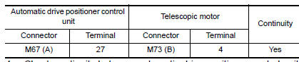
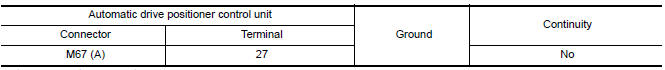
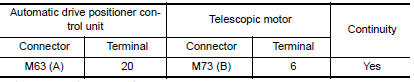
4. CHECK TELESCOPIC SENSOR POWER SUPPLY CIRCUIT
- Turn ignition switch OFF.
- Disconnect automatic drive positioner control unit.
- Check continuity between automatic drive positioner control unit harness connector and telescopic motor harness connect
- Check continuity between automatic drive positioner control unit harness connector and ground.
5. CHECK TELESCOPIC SENSOR GROUND CIRCUIT
- Turn ignition switch OFF.
- Disconnect automatic drive positioner control unit.
- Check continuity between automatic drive positioner control unit harness connector and telescopic motor harness connector.
 Tilt sensor
Description
The tilt sensor is installed to the steering column assembly.
The pulse signal is input to the driver seat control unit when the tilt
is operated.
The driver seat control unit c ...
 Mirror sensor
DRIVER SIDE
DRIVER SIDE : Description
The mirror sensor LH is installed to the door mirror LH.
The resistance of 2 sensors (horizontal and vertical) is changed
when the door mirror LH is ope ...
Other materials:
P1610 lock mode
Description
Performs ID verification through BCM and Intelligent Key
when push-button ignition switch is pressed.
Prohibits the start of engine when an unregistered ID of Intelligent Key is
used.
DTC Logic
DTC DETECTION LOGIC
DTC CONFIRMATION PROCEDURE
1.PERFORM DTC CONFIRMATION PROCED ...
Inspection and adjustment
Preliminary Check
1. FOREIGN OBJECTS
Check the following:
objects on or behind the seats that could cause binding
objects under the seats that may be interfering with the seat's
moving parts
objects under pedals that may interfere with movement
Are there any foreign objects that coul ...
Air mix door control system
System Diagram
System Description
The air mix doors are automatically controlled so that in-vehicle temperature
is maintained at a predetermined
value by the temperature setting, ambient temperature, intake temperature and
amount of sunload.
SYSTEM OPERATION
The A/C auto amp. receiv ...
Nissan Maxima Owners Manual
- Illustrated table of contents
- Safety-Seats, seat belts and supplemental restraint system
- Instruments and controls
- Pre-driving checks and adjustments
- Monitor, climate, audio, phone and voice recognition systems
- Starting and driving
- In case of emergency
- Appearance and care
- Do-it-yourself
- Maintenance and schedules
- Technical and consumer information
Nissan Maxima Service and Repair Manual

0.0063