Nissan Maxima Service and Repair Manual: Mirror sensor
DRIVER SIDE
DRIVER SIDE : Description
- The mirror sensor LH is installed to the door mirror LH.
- The resistance of 2 sensors (horizontal and vertical) is changed when the door mirror LH is operated.
- Automatic drive positioner control unit calculates the door mirror position according to the change of the voltage of 2 sensor input terminals.
DRIVER SIDE : Component Function Check
1. CHECK FUNCTION
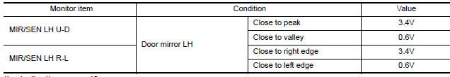
- Select "MIR/SEN LH U-D", "MIR/SEN LH R-L" in "DATA MONITOR" with CONSULT.
- Check mirror sensor (driver side) signal under the following condition.
DRIVER SIDE : Diagnosis Procedure
1. CHECK DOOR MIRROR LH SENSOR SIGNAL
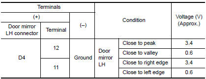
- Turn ignition switch to ACC.
- Check voltage between door mirror LH harness connector and ground.
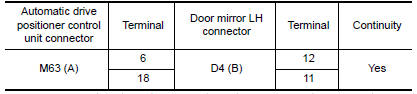
2. CHECK DOOR MIRROR LH SENSOR CIRCUIT 1
- Turn ignition switch OFF.
- Disconnect automatic drive positioner control unit and door mirror LH connector.
- Check continuity between automatic drive positioner control unit harness connector and door mirror LH harness connector.
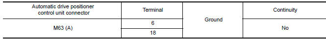
- Check continuity between automatic drive positioner control unit harness connector and ground.
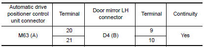
3. CHECK DOOR MIRROR LH SENSOR CIRCUIT 2
- Check continuity between automatic drive positioner control unit harness connector and door mirror LH harness connector.
- Check continuity between automatic drive positioner control unit harness connector and ground.
4. CHECK TILT MOTOR ADJUSTING OPERATION
- Connect automatic drive positioner control unit and door mirror LH.
- Turn ignition switch ON.
- Check tilt motor adjusting operation with memory function.
5. CHECK INTERMITTENT INCIDENT
PASSENGER SIDE
PASSENGER SIDE : Description
- The mirror sensor RH is installed to the door mirror RH.
- The resistance of 2 sensors (horizontal and vertical) is changed when the door mirror RH is operated.
- Automatic drive positioner control unit calculates the door mirror position according to the change of the voltage of 2 sensor input terminals.
PASSENGER SIDE : Component Function Check
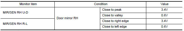
1. CHECK FUNCTION
- Select "MIR/SEN RH U-D", "MIR/SEN RH R-L" in "DATA MONITOR" with CONSUL.
- Check the mirror sensor RH signal under the following conditions.
PASSENGER SIDE : Diagnosis Procedure
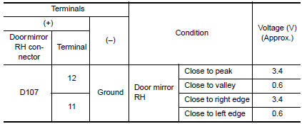
1. CHECK DOOR MIRROR RH SENSOR SIGNAL
- Turn ignition switch to ACC.
- Check voltage between door mirror RH harness connector and ground.
2. CHECK DOOR MIRROR RH SENSOR CIRCUIT 1
- Turn ignition switch OFF.
- Disconnect automatic drive positioner control unit and door mirror RH.
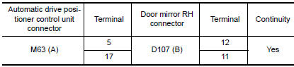
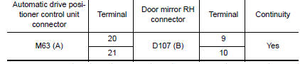
- Check continuity between automatic drive positioner control unit harness connector and door mirror RH harness connector.
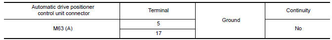
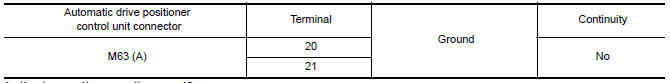
- Check continuity between automatic drive positioner control unit harness connector and ground.
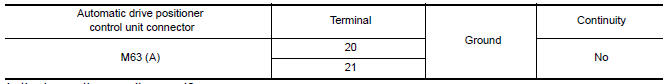
3. CHECK DOOR MIRROR RH SENSOR CIRCUIT 2
- Check continuity between automatic drive positioner control unit harness connector and door mirror RH harness connector.
- Check continuity between automatic drive positioner control unit harness connector and ground.
4. CHECK TILT MOTOR ADJUSTING OPERATION
- Connect automatic drive positioner control unit and door mirror RH.
- Turn ignition switch ON.
- Check tilt motor adjusting operation with memory function.
5. CHECK INTERMITTENT INCIDENT
 Telescopic sensor
Description
The telescopic sensor is installed to the steering column assembly.
The pulse signal is input to the driver seat control unit when
telescopic is performed.
The driver seat contr ...
 Sliding motor
Description
The sliding motor LH is installed to the seat frame.
The sliding motor LH is activated with the driver seat control unit.
The seat is slid forward/backward by changing the rotation ...
Other materials:
Antenna AMP.
Removal and Installation
REMOVAL
Remove the rear pillar finisher RH. Refer to INT-36, "Exploded
View".
Detach the antenna amp. harness clip (A).
Disconnect the harness connectors (B) from the antenna amp.
(1).
Remove the antenna amp. screw (C) and the antenna amp. (1).
...
Precaution
PRECAUTIONS
Precautions for Trouble Diagnosis
CAUTION:
Never apply 7.0 V or more to the measurement terminal.
Use a tester with open terminal voltage of 7.0 V or less.
Turn the ignition switch OFF and disconnect the battery cable from the
negative terminal when checking the harness.
P ...
Wiring diagram
BCM (BODY CONTROL MODULE)
Wiring Diagram
...
Nissan Maxima Owners Manual
- Illustrated table of contents
- Safety-Seats, seat belts and supplemental restraint system
- Instruments and controls
- Pre-driving checks and adjustments
- Monitor, climate, audio, phone and voice recognition systems
- Starting and driving
- In case of emergency
- Appearance and care
- Do-it-yourself
- Maintenance and schedules
- Technical and consumer information
Nissan Maxima Service and Repair Manual

0.0057