Nissan Maxima Service and Repair Manual: Climate controlled seat
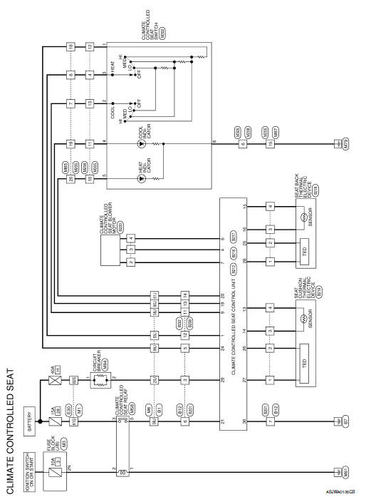
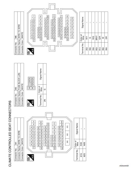
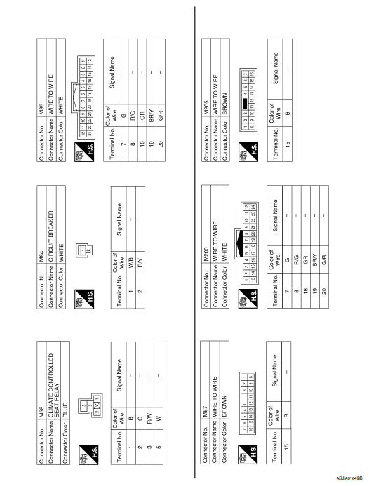
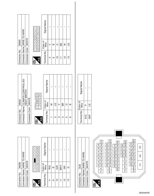
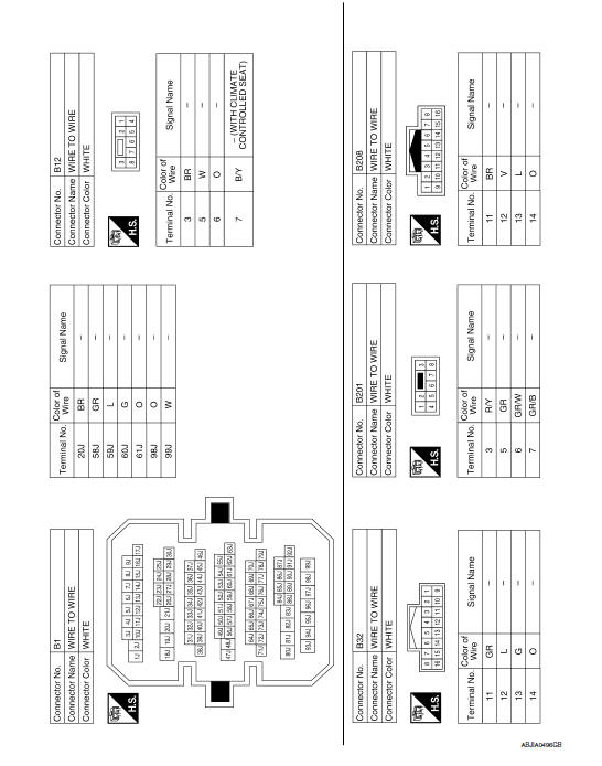
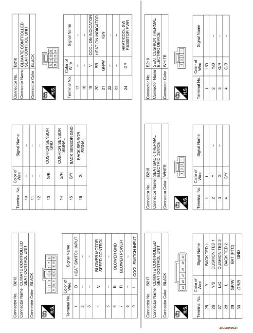
Wiring Diagram
 Lumbar support system
Wiring Diagram
...

Other materials:
Precaution
Precaution for Supplemental Restraint System (SRS) "AIR BAG" and "SEAT
BELT
PRE-TENSIONER"
The Supplemental Restraint System such as "AIR BAG" and "SEAT BELT PRE-TENSIONER",
used along
with a front seat belt, helps to reduce the risk or severity of injury to the
driver ...
Trunk open function
TRUNK LID OPENER SWITCH
TRUNK LID OPENER SWITCH : System Diagram
TRUNK LID OPENER SWITCH : System Description
TRUNK LID OPENER OPERATION
When trunk lid opener switch is ON, BCM opens trunk release solenoid.
BCM can open trunk lid opener actuator when
vehicle speed is less than 5 ...
ADP branch line circuit
Diagnosis Procedure
1.CHECK CONNECTOR
Turn the ignition switch OFF.
Disconnect the battery cable from the negative terminal.
Check the following terminals and connectors for damage, bend and
loose connection (unit side and connector
side).
Driver seat control unit
Harness connec ...
Nissan Maxima Owners Manual
- Illustrated table of contents
- Safety-Seats, seat belts and supplemental restraint system
- Instruments and controls
- Pre-driving checks and adjustments
- Monitor, climate, audio, phone and voice recognition systems
- Starting and driving
- In case of emergency
- Appearance and care
- Do-it-yourself
- Maintenance and schedules
- Technical and consumer information
Nissan Maxima Service and Repair Manual

0.0058