Nissan Maxima Service and Repair Manual: Lumbar support system
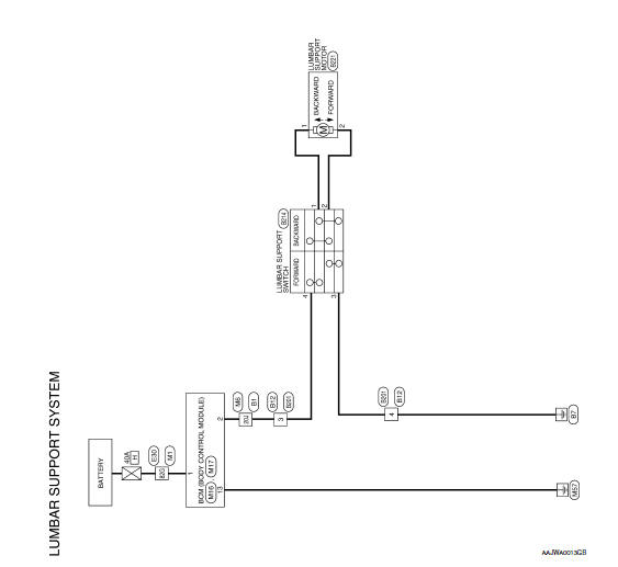
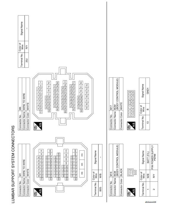
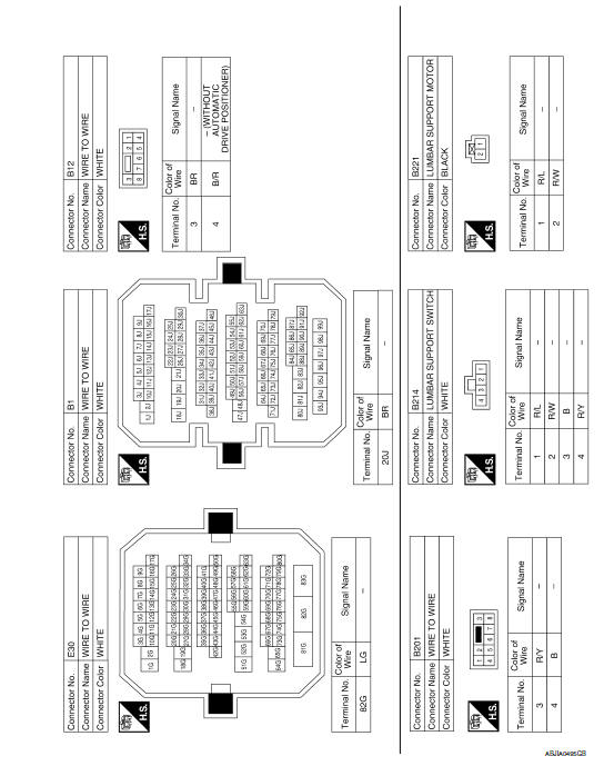
Wiring Diagram
 Heated seat
Wiring Diagram
...
 Climate controlled seat
Wiring Diagram
...
Other materials:
Climate controlled seat switch
Description
Provides inputs to the climate controlled seat control unit for climate
controlled seat operation.
Component Function Check
1.CHECK CLIMATE CONTROLLED SEAT SWITCH FUNCTION
Turn the climate controlled seat switch to the H (Heat) LO, MED, and HI
positions and the C (Cool) LO, MED, ...
P0128 thermostat function
DTC Logic
DTC DETECTION LOGIC
NOTE:
If DTC P0128 is displayed with DTC P0300, P0301, P0302, P0303, P0304, P0305 or
P0306, first perform
the trouble diagnosis for DTC P0300, P0301, P0302, P0303, P0304, P0305, P0306.
Engine coolant temperature has not risen enough to open the thermostat even ...
CVT shift selector
Exploded View
CVT shift selector handle
Shift selector handle clip
Shift selector handle cover
CVT shift selector assembly
Shift lock unit
:Front
Removal and Installation
REMOVAL
Disconnect the battery neg ...
Nissan Maxima Owners Manual
- Illustrated table of contents
- Safety-Seats, seat belts and supplemental restraint system
- Instruments and controls
- Pre-driving checks and adjustments
- Monitor, climate, audio, phone and voice recognition systems
- Starting and driving
- In case of emergency
- Appearance and care
- Do-it-yourself
- Maintenance and schedules
- Technical and consumer information
Nissan Maxima Service and Repair Manual

0.0062