Nissan Maxima Service and Repair Manual: Heated seat
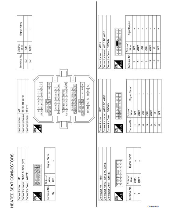
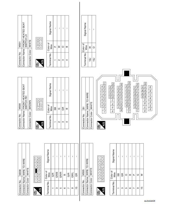
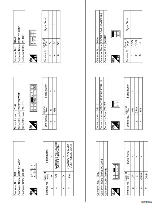
Wiring Diagram

 Power seat for passenger side
Wiring Diagram
...
 Lumbar support system
Wiring Diagram
...
Other materials:
Radiator core support
Exploded View
Radiator core support
Bolts
Removal and Installation
REMOVAL
Remove front bumper. Refer to EXT-16, "Removal and Installation".
Remove front combination lamps (LH/RH). Refer to EXL-154, "Removal
and Installation" (Xenon Type),
EXL-31 ...
Mudguard
Exploded View
Mudguard
Clip C205
Clip CF118
Front
Removal and Installation
REMOVAL
Remove the clips located on the underbody.
Remove the center mudguard front and rear screws.
Remove the rear wind deflector bolt. Refer to EXT-24, "Removal and
Installation".
Release t ...
U1216 AV control unit
Description
Part name
Description
AV CONTROL UNIT
It is the master unit of the MULTI AV system and it is connected
to each control unit by means of communication. It operates each
system according to communication signals from the AV contro ...
Nissan Maxima Owners Manual
- Illustrated table of contents
- Safety-Seats, seat belts and supplemental restraint system
- Instruments and controls
- Pre-driving checks and adjustments
- Monitor, climate, audio, phone and voice recognition systems
- Starting and driving
- In case of emergency
- Appearance and care
- Do-it-yourself
- Maintenance and schedules
- Technical and consumer information
Nissan Maxima Service and Repair Manual

0.0058