
Nissan Maxima Service and Repair Manual: Trunk lid
TRUNK LID ASSEMBLY
TRUNK LID ASSEMBLY : Removal and Installation
CAUTION:
- Use two people when removing or installing trunk lid assembly due to its heavy weight.
- Use protective tape or shop cloths to protect surrounding components from damage during removal and installation of trunk lid assembly.
REMOVAL
- Remove trunk lid finisher. Refer to INT-36, "Removal and Installation".
- Disconnect the harness connectors in the trunk lid, remove the harness clips, and then pull the harness out of the trunk lid.
- Remove the nuts and the trunk lid assembly.
INSTALLATION
Installation is in the reverse order of removal.
CAUTION:
- After installation, check trunk lid open/close, lock/unlock operation.
- After installation, perform the trunk lid assembly adjustment procedure
TRUNK LID ASSEMBLY : Adjustment
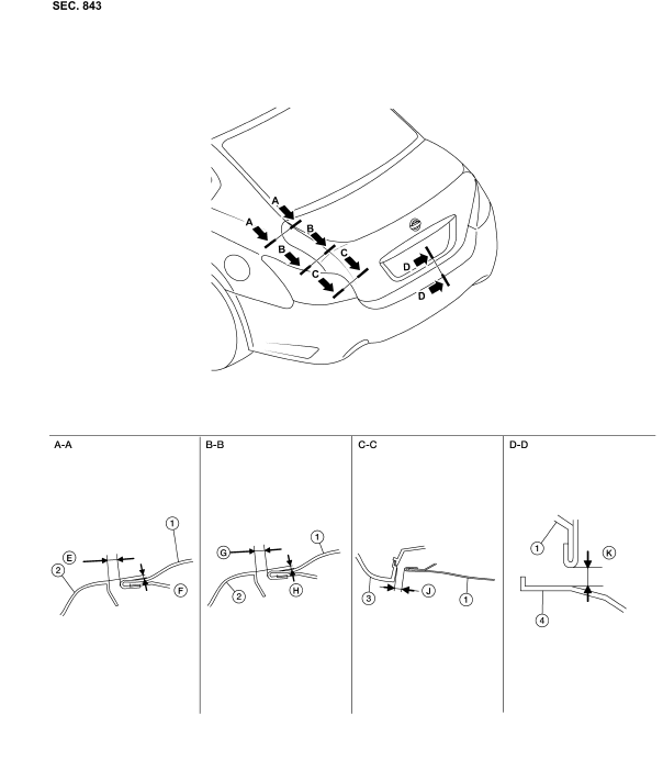
- Trunk lid assembly
- Body side outer
- Rear combination lamp
- Rear bumper fascia
 Front
Front
Check the clearance and the surface height between trunk lid and each part by visual inspection and tactile feel
If the clearance and the surface height are out of specification, adjust them according to the adjustment procedures.
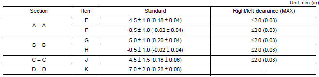
LONGITUDINAL CLEARANCE
Trunk Lid Removed From Hinge
- Loosen the trunk lid to hinge bolts.
- Move the trunk lid so that the clearance measurements are within specifications provided.
- Tighten the trunk lid to hinge bolts.
Trunk Lid Hinge Removed From Vehicle
- Remove the parcel shelf trim. Refer to INT-28, "Removal and Installation".
- Loosen the hinge to parcel shelf bolts.
- Move the trunk lid so that the clearance measurements are within specifications provided.
- Tighten the hinge to parcel shelf bolts.
- Install the parcel shelf trim. Refer to INT-28, "Removal and Installation".
SURFACE HEIGHT ADJUSTMENT
- Loosen the bumper rubber.
- Loosen the striker bolts.
- Lift up the trunk lid approx. 100 - 150 mm (3. 94 - 5. 91 in) then close it lightly. Make sure it engages firmly with the trunk lid closed.
- Tighten the trunk lid striker.
TRUNK LID LOCK
TRUNK LID LOCK : Removal and Installation
LOCK
Removal
- Remove the trunk lid finisher. Refer to INT-36, "Removal and Installation".
- Remove the trunk lid lock bolts.
- Disconnect the harness connector and emergency release handle from the trunk lid lock and remove.
Installation
Installation is in the reverse order of removal.
- Remove the trunk rear finisher. Refer to INT-36, "Removal and Installation".
- Remove the bolts and the striker.
Installation
Installation is in the reverse order of removal.
NOTE: Align the trunk lid lock. Refer to DLK-228, "TRUNK LID LOCK : Removal and Installation".
TRUNK LID STAY
TRUNK LID STAY : Disposal
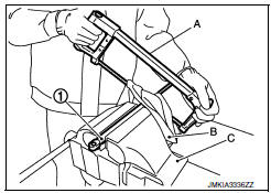
- Fix trunk lid stay (1) using a vise (C).
- Using hacksaw (A) slowly make 2 holes in the trunk lid stay, in numerical order as shown.
CAUTION:
- When cutting a hole on trunk lid stay, always cover hacksaw with a shop cloth (B) to avoid scattering metal fragments or oil.
- Wear eye protection (safety glasses).
- Wear gloves.
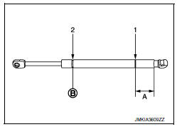
A: 20 mm (0. 8 in)
B: Cut at the groove.
 Door lock
FRONT DOOR LOCK
FRONT DOOR LOCK : Exploded View
Door key cylinder outside handle escutcheon
assembly (drivers side)
Outside handle escutcheon (passenger side)
Rear gasket
Striker
...
 Door switch
Exploded View
Door switch
Removal and Installation
REMOVAL
Remove the door switch screw (A).
Disconnect the harness connector from the door switch (1) and
remove
INSTALLAT ...
Other materials:
C1110, C1153, C1170 ABS actuator and electric unit (control unit)
DTC Logic
DTC DETECTION LOGIC
DTC CONFIRMATION PROCEDURE
1.CHECK SELF-DIAGNOSIS RESULTS
Check the self-diagnosis results.
Diagnosis Procedure
1.REPLACE ABS ACTUATOR AND ELECTRIC UNIT (CONTROL UNIT)
CAUTION:
Replace ABS actuator and electric unit (control unit) when self-diagnostic
...
Unit disassembly and assembly
COOLING FAN
Disassembly and Assembly of Cooling Fan
Fan blade
Fan shroud
Fan motor
DISASSEMBLY
Remove fan blade nut.
Remove fan blade from fan motor.
Remove fan motor bolts and remove fan motor from fan shroud.
ASSEMBLY
Assembly is in the reverse order of disassembly. ...
Audio display unit
Removal and Installation
Audio display unit bracket
Audio display unit
Cluster lid D
Multifunction switch
Audio display unit bracket screws
Audio display unit screws
Metal Clip
REMOVAL
Remove cluster lid D. Refer to IP-18, "Removal and Installation".
...
Nissan Maxima Owners Manual
- Illustrated table of contents
- Safety-Seats, seat belts and supplemental restraint system
- Instruments and controls
- Pre-driving checks and adjustments
- Monitor, climate, audio, phone and voice recognition systems
- Starting and driving
- In case of emergency
- Appearance and care
- Do-it-yourself
- Maintenance and schedules
- Technical and consumer information
Nissan Maxima Service and Repair Manual

0.0135