Nissan Maxima Service and Repair Manual: B2618 BCM
Description
BCM controls the various electrical components and simultaneously supplies power according to the power supply position.
BCM checks the power supply position internally.
DTC Logic
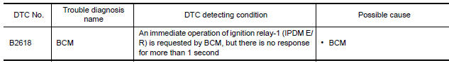
DTC DETECTION LOGIC
NOTE:
- If DTC B2618 is displayed with DTC U1000, first perform the trouble diagnosis for DTC U1000. Refer to PCS-44, "DTC Logic".
- If DTC B2618 is displayed with DTC U1010, first perform the trouble diagnosis for DTC U1010. Refer to PCS-45, "DTC Logic".
DTC CONFIRMATION PROCEDURE
1. PERFORM DTC CONFIRMATION PROCEDURE
- Turn ignition switch ON under the following conditions, and wait for at least 1 second.
- CVT selector lever is in the P or N position
- Release brake pedal
- Check "Self diagnostic result" with CONSULT.
Diagnosis Procedure
1. INSPECTION START
- Turn ignition switch ON.
- Select "Self diagnostic result" mode with CONSULT.
- Touch "ERASE".
- Perform DTC Confirmation Procedure.
 B2616 ignition relay circuit
Description
BCM controls the various electrical components and simultaneously supplies
power according to the power
supply position.
BCM checks the power supply position internally.
DTC Logic ...
 B261A push-button ignition switch
Description
IPDM E/R transmits the push-button ignition switch status via CAN
communication to BCM. BCM receives
push-button ignition switch status by hardwire input. BCM compares the 2 signals
...
Other materials:
Mudguard
Exploded View
Mudguard
Clip C205
Clip CF118
Front
Removal and Installation
REMOVAL
Remove the clips located on the underbody.
Remove the center mudguard front and rear screws.
Remove the rear wind deflector bolt. Refer to EXT-24, "Removal and
Installation".
Release t ...
Low brake fluid warning light
When the ignition switch is placed in the ON
position, the light warns of a low brake fluid level.
If the light comes on while the engine is running,
with the parking brake not applied, stop the vehicle
and perform the following:
1. Check the brake fluid level. Add brake fluid
as necessary. ...
Cooling fan control
System Diagram
System Description
INPUT/OUTPUT SIGNAL CHART
*1: The ECM determines the start signal status by the signals of engine speed
and battery voltage.
*2: This signal is sent to ECM via the CAN communication line.
SYSTEM DESCRIPTION
The ECM controls the cooling fan correspon ...
Nissan Maxima Owners Manual
- Illustrated table of contents
- Safety-Seats, seat belts and supplemental restraint system
- Instruments and controls
- Pre-driving checks and adjustments
- Monitor, climate, audio, phone and voice recognition systems
- Starting and driving
- In case of emergency
- Appearance and care
- Do-it-yourself
- Maintenance and schedules
- Technical and consumer information
Nissan Maxima Service and Repair Manual

0.0053