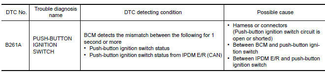
Nissan Maxima Service and Repair Manual: B261A push-button ignition switch
Description
IPDM E/R transmits the push-button ignition switch status via CAN communication to BCM. BCM receives push-button ignition switch status by hardwire input. BCM compares the 2 signals for mismatch.
DTC Logic
DTC DETECTION LOGIC
NOTE:
- If DTC B261A is displayed with DTC U1000, first perform the trouble diagnosis for DTC U1000. Refer to PCS-44, "DTC Logic".
- If DTC B261A is displayed with DTC U1010, first perform the trouble diagnosis for DTC U1010. Refer to PCS-45, "DTC Logic".
DTC CONFIRMATION PROCEDURE
1.PERFORM DTC CONFIRMATION PROCEDURE
- Press the push-button ignition switch under the following conditions and wait for at least 1 second.
- CVT selector lever is in the P position
- Do not depress brake pedal.
- Check "Self diagnostic result" with CONSULT.
Diagnosis Procedure
1. CHECK PUSH-BUTTON IGNITION SWITCH OPERATION
Press push-button ignition switch and check if it turns to ON.
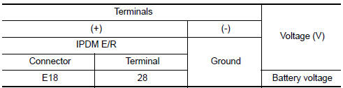
2. CHECK IGNITION SWITCH OUTPUT SIGNAL (IPDM E/R)
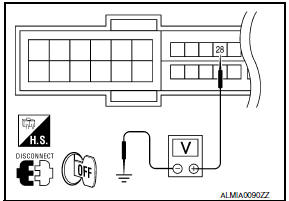
- Turn ignition switch OFF.
- Disconnect push-button ignition switch.
- Check voltage between IPDM E/R harness connector and ground.
3. CHECK PUSH-BUTTON IGNITION SWITCH CIRCUIT (IPDM E/R)
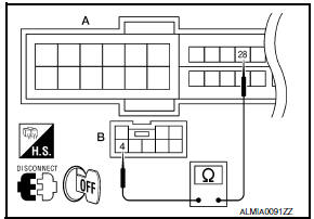
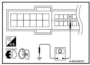
- Disconnect IPDM E/R and BCM.
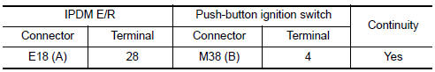
- Check continuity between IPDM E/R harness connector (A) and push-button ignition switch harness connector (B).
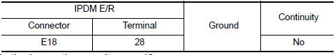
- Check continuity between IPDM E/R harness connector and ground.
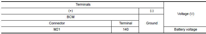
4. CHECK IGNITION SWITCH OUTPUT SIGNAL (BCM)
- Disconnect push-button ignition switch.
- Check voltage between BCM harness connector and ground.
5. CHECK PUSH-BUTTON IGNITION SWITCH CIRCUIT (BCM)
- Disconnect BCM and IPDM E/R.
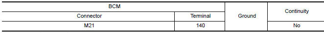
- Check continuity between BCM harness connector and push-button ignition switch harness connector.
- Check continuity between BCM harness connector and ground.

 B2618 BCM
Description
BCM controls the various electrical components and simultaneously supplies
power according to the power
supply position.
BCM checks the power supply position internally.
DTC Logic ...
 Power supply and ground circuit
BCM
BCM : Diagnosis Procedure
1. CHECK FUSE AND FUSIBLE LINK
Check if the following BCM fuses or fusible link are blown.
2. CHECK POWER SUPPLY CIRCUIT
Turn ignition switch OFF.
Disconnec ...
Other materials:
Shift lock release
If the battery charge is low or discharged, the
shift lever may not be moved from the P (Park)
position even with the brake pedal depressed
and the shift lever button pressed.
It will be necessary to jump start or have your
battery charged, For additional information, refer
to "Jump star ...
Precaution
PRECAUTIONS
Precaution for Supplemental Restraint System (SRS) "AIR BAG" and "SEAT BELT
PRE-TENSIONER"
The Supplemental Restraint System such as "AIR BAG" and "SEAT BELT
PRE-TENSIONER", used along
with a front seat belt, helps to reduce the risk or severity of injury to the
driver and fron ...
Excessive ABS function operation frequency
Diagnosis Procedure
1.CHECK START
Check front and rear brake force distribution using a brake tester.
2.CHECK FRONT AND REAR AXLE
Make sure that there is no excessive play in the front and rear axles.
3.CHECK WHEEL SENSOR AND SENSOR ROTOR
Check the following:
Wheel sensor installation for ...
Nissan Maxima Owners Manual
- Illustrated table of contents
- Safety-Seats, seat belts and supplemental restraint system
- Instruments and controls
- Pre-driving checks and adjustments
- Monitor, climate, audio, phone and voice recognition systems
- Starting and driving
- In case of emergency
- Appearance and care
- Do-it-yourself
- Maintenance and schedules
- Technical and consumer information
Nissan Maxima Service and Repair Manual

0.0055