Nissan Maxima Service and Repair Manual: Diagnosis system (ipdm E/R)
Diagnosis Description
AUTO ACTIVE TEST
Description
In auto active test mode, the IPDM E/R sends a drive signal to the following systems to check their operation.
- Oil pressure warning lamp
- Front wiper (LO, HI)
- Parking lamps
- Side marker lamps
- License plate lamps
- Tail lamps
- Front fog lamps (if equipped)
- Headlamps (LO, HI)
- A/C compressor (magnet clutch)
- Cooling fans
Operation Procedure
- Close the hood and lift the wiper arms from the windshield. (Prevent windshield damage due to wiper operation) NOTE: When auto active test is performed with hood opened, sprinkle water on windshield beforehand.
- Turn ignition switch OFF.
- Turn the ignition switch ON, and within 20 seconds, press the front door switch LH 10 times. Then turn the ignition switch OFF. CAUTION: Close front door RH.
- Turn the ignition switch ON within 10 seconds. After that the horn sounds once and the auto active test starts.
- The oil pressure warning lamp starts blinking when the auto active test starts.
- After a series of the following operations is repeated 3 times, auto active test is completed.
NOTE: When auto active test mode has to be cancelled halfway through test, turn ignition switch OFF.
CAUTION:
- If auto active test mode cannot be actuated, check door switch system. Refer to DLK-67, "Component Function Check".
- Do not start the engine.
Inspection in Auto Active Test Mode
When auto active test mode is actuated, the following 6 steps are repeated 3 times.
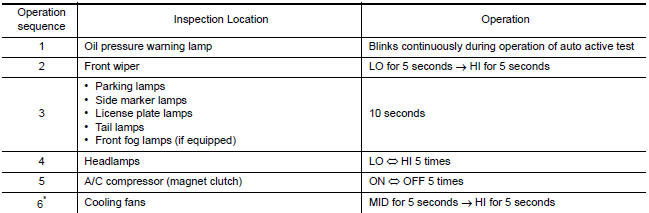
*: Outputs duty ratio of 50% for 5 seconds → duty ratio of 100% for 5 seconds on the cooling fan control module.
Concept of auto active test
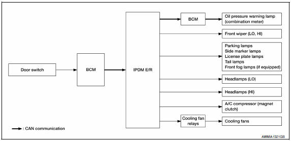
- IPDM E/R starts the auto active test with the door switch signals
transmitted by BCM via CAN communication.
Therefore, the CAN communication line between IPDM E/R and BCM is considered normal if the auto active test starts successfully.
- The auto active test facilitates troubleshooting if any systems controlled by IPDM E/R cannot be operated
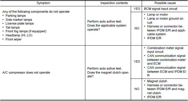
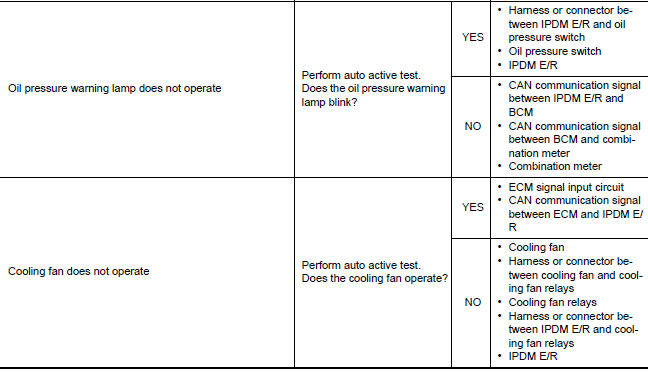
Diagnosis chart in auto active test mode
CONSULT Function (IPDM E/R)
APPLICATION ITEM
CONSULT performs the following functions via CAN communication with IPDM E/R.
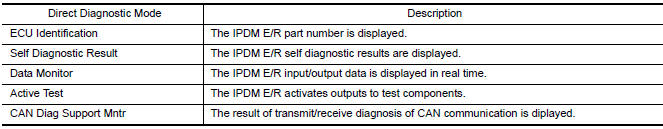
ECU IDENTIFICATION
The IPDM E/R part number is displayed.
SELF DIAGNOSTIC RESULT
Refer to PCS-27, "DTC Index".
DATA MONITOR
ACTIVE TEST
CAN DIAG SUPPORT MNTR
 Diagnosis system (BCM)
COMMON ITEM
COMMON ITEM : CONSULT Function (BCM - COMMON ITEM)
APPLICATION ITEM
CONSULT performs the following functions via CAN communication with BCM.
SYSTEM APPLICATION
BCM can perform the f ...

Other materials:
Preparation
Special Service Tools
The actual shapes of Kent-Moore tools may differ from those of special
service tools illustrated here.
Commercial Service Tools
...
Removal and installation
COMPRESSOR
Removal and Installation for Compressor
REMOVAL
CAUTION: Before servicing, turn the ignition
switch off, disconnect both battery terminals and wait at least three
minutes.
Disconnect the battery negative and positive terminals. Refer to
PG-67, "Removal and Installation ( ...
Diagnosis and repair workflow
Work Flow
WORK FLOW
DETAILED FLOW
1. GET INFORMATION FOR SYMPTOM
Get the detailed information from the customer about the symptom (the
condition and the environment when the incident/malfunction occurred).
2. CHECK DTC
Check DTC.
Perform the following procedure if DTC is displayed.
...
Nissan Maxima Owners Manual
- Illustrated table of contents
- Safety-Seats, seat belts and supplemental restraint system
- Instruments and controls
- Pre-driving checks and adjustments
- Monitor, climate, audio, phone and voice recognition systems
- Starting and driving
- In case of emergency
- Appearance and care
- Do-it-yourself
- Maintenance and schedules
- Technical and consumer information
Nissan Maxima Service and Repair Manual

0.0108