
Nissan Maxima Service and Repair Manual: Diagnosis system (BCM)
COMMON ITEM
COMMON ITEM : CONSULT Function (BCM - COMMON ITEM)
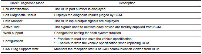
APPLICATION ITEM
CONSULT performs the following functions via CAN communication with BCM.
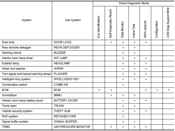
SYSTEM APPLICATION
BCM can perform the following functions.
HEADLAMP
HEADLAMP : CONSULT Function (BCM - HEAD LAMP)
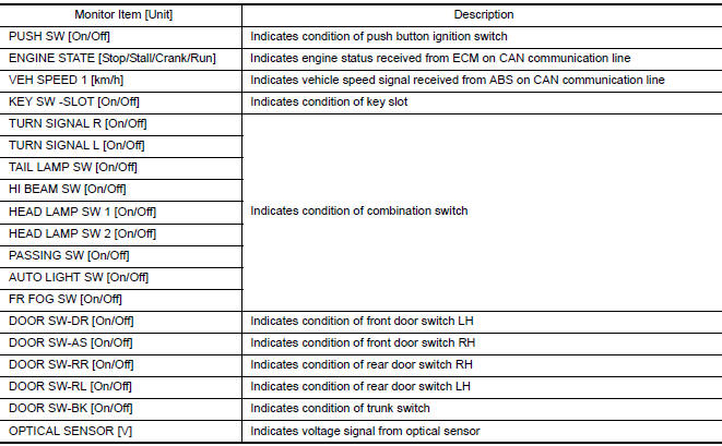
DATA MONITOR
ACTIVE TEST

WORK SUPPORT
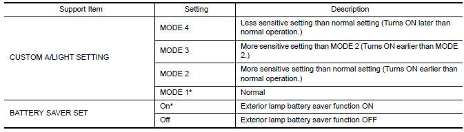
* : Initial setting
FLASHER
FLASHER : CONSULT Function (BCM - FLASHER)
DATA MONITOR
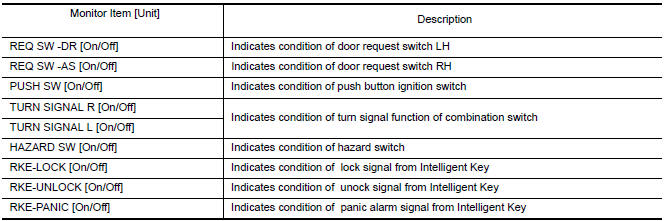
ACTIVE TEST

WORK SUPPORT
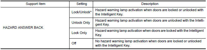
* : Initial setting
COMB SW
COMB SW : CONSULT Function (BCM-COMB SW)
DATA MONITOR
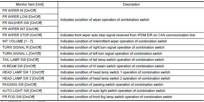
BATTERY SAVER
BATTERY SAVER : CONSULT Function (BCM - BATTERY SAVER)
DATA MONITOR
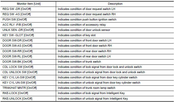
ACTIVE TEST

WORK SUPPORT

* : Initial setting
 Combination switch reading system
System Diagram
System Description
OUTLINE
BCM reads the status of the combination switch (light, turn
signal, wiper and washer) and recognizes the status of each switch.
BCM has a combina ...
 Diagnosis system (ipdm E/R)
Diagnosis Description
AUTO ACTIVE TEST
Description
In auto active test mode, the IPDM E/R sends a drive signal to the following
systems to check their operation.
Oil pressure warning lamp
F ...
Other materials:
Brake master cylinder
Exploded View
Reservoir cap
Oil strainer (blue)
Master cylinder assembly
Brake fluid level switch harness connector
O-ring
PBC (Poly Butyl Cuprysil) grease or
silicone-based grease
Removal and Installation
CAUTION:
Do not to splash brake fluid on painted areas; ...
Audio antenna
Location of Antenna
Audio unit
Audio unit antenna feeder
In-line connectors M103, M501
Antenna amp.
Window antenna
Window Antenna Repair
ELEMENT CHECK
Attach probe circuit tester (ohm setting) to antenna terminal on
each side
When measuring continuity, wrap tin ...
C1708 - C1711 data from transmitter not being received
Description
Tire pressure data for one or more transmitters is not being received by the
BCM.
DTC Logic
NOTE: The Signal Tech II Tool (J-50190) can
be used to perform the following functions. Refer to the Signal Tech II User
Guide for additional information.
Activate and display T ...
Nissan Maxima Owners Manual
- Illustrated table of contents
- Safety-Seats, seat belts and supplemental restraint system
- Instruments and controls
- Pre-driving checks and adjustments
- Monitor, climate, audio, phone and voice recognition systems
- Starting and driving
- In case of emergency
- Appearance and care
- Do-it-yourself
- Maintenance and schedules
- Technical and consumer information
Nissan Maxima Service and Repair Manual

0.0597